Detection device and detection method for military thermal image sight
A technology of detection equipment and sight sights, which is applied in the testing of machine/structural components, measuring devices, optical instrument testing, etc. Detect problems such as the quality of infrared detection components
- Summary
- Abstract
- Description
- Claims
- Application Information
AI Technical Summary
Problems solved by technology
Method used
Image
Examples
Embodiment 1
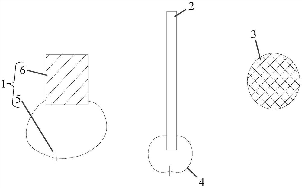
[0057] It records a detection equipment for military thermal imaging sights, such as figure 1 as well as Figure 4 with Figure 5 shown, which includes:
[0058] A variable temperature heat source 1, the variable temperature heat source 1 changes its temperature under control; the variable temperature heat source 1 includes: a heat source temperature control mechanism 5 and a heat conductor 6 made of red copper; the heat source temperature control mechanism 5 includes: The second controller, and the Peltier semiconductor device arranged on the heat conductor 6; the second controller heats the heat conductor 6 through the Peltier semiconductor device according to the Peltier principle; the The heat conductor 6 is also provided with a temperature sensor for detecting its temperature, and the second controller communicates with the temperature sensor to control the required power and current direction of the Peltier semiconductor device;
[0059] The blocking grid 2 is made of...
Embodiment 2
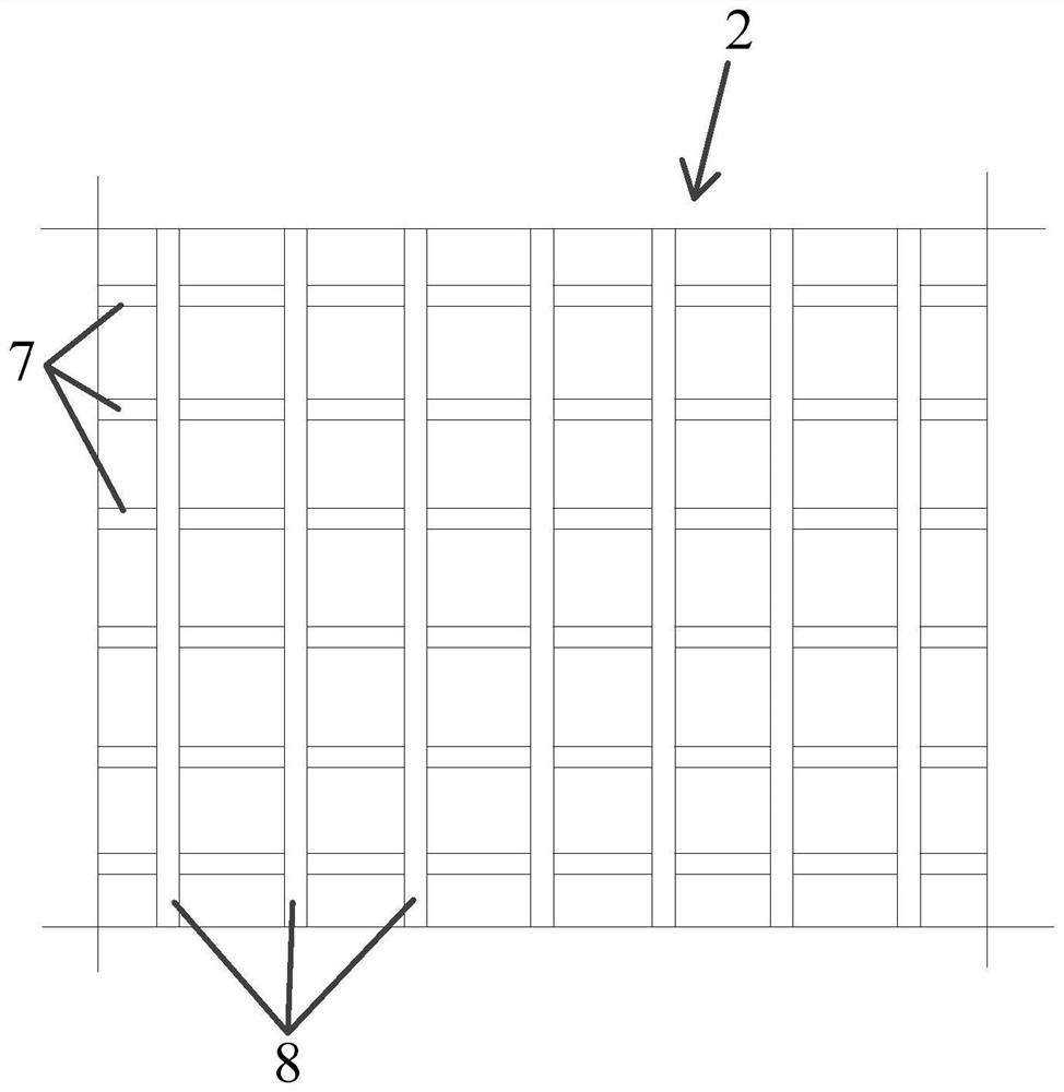
[0068] The difference between this embodiment and embodiment 1 is that, as figure 2 As shown, the detection equipment for military thermal imaging sights includes:
[0069] A variable temperature heat source 1, the variable temperature heat source 1 changes its temperature under control; the variable temperature heat source 1 includes: a heat source temperature control mechanism 5 and a heat conductor 6 made of red copper; the heat source temperature control mechanism 5 includes: The second controller, and the Peltier semiconductor device arranged on the heat conductor 6; the second controller heats the heat conductor 6 through the Peltier semiconductor device according to the Peltier principle; the The heat conductor 6 is also provided with a temperature sensor for detecting its temperature, and the second controller communicates with the temperature sensor to control the required power and current direction of the Peltier semiconductor device;
[0070] The blocking grid 2 ...
Embodiment 3
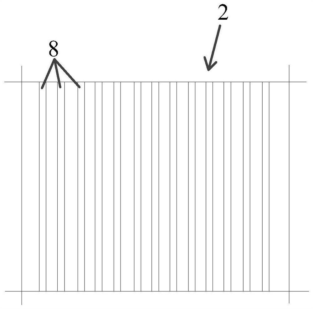
[0073] The difference between this embodiment and embodiment 1 is that, as image 3 As shown, the detection equipment for military thermal imaging sights includes:
[0074] A variable temperature heat source 1, the variable temperature heat source 1 changes its temperature under control; the variable temperature heat source 1 includes: a heat source temperature control mechanism 5 and a heat conductor 6 made of red copper; the heat source temperature control mechanism 5 includes: The second controller, and the Peltier semiconductor device arranged on the heat conductor 6; the second controller heats the heat conductor 6 through the Peltier semiconductor device according to the Peltier principle; the The heat conductor 6 is also provided with a temperature sensor for detecting its temperature, and the second controller communicates with the temperature sensor to control the required power and current direction of the Peltier semiconductor device;
[0075] The blocking grid 2 i...
PUM
 Abstract
Description
Claims
Application Information
 - R&D Engineer
- R&D Manager
- IP Professional
- Industry Leading Data Capabilities
- Powerful AI technology
- Patent DNA Extraction
Browse by: Latest US Patents, China's latest patents, Technical Efficacy Thesaurus, Application Domain, Technology Topic, Popular Technical Reports.
© 2024 PatSnap. All rights reserved.Legal|Privacy policy|Modern Slavery Act Transparency Statement|Sitemap|About US| Contact US: help@patsnap.com


