Target tracking method, system and electronic device

A target tracking and target technology, applied in the field of digital images, can solve problems such as motion overshoot and oscillation, and achieve the effects of good versatility, elimination of oscillation, and convenient debugging

Active Publication Date: 2022-07-12
南京博蓝奇智能科技有限公司
View PDF5 Cites 0 Cited by
  • Summary
  • Abstract
  • Description
  • Claims
  • Application Information

AI Technical Summary

Problems solved by technology

[0003] In order to solve the problem of motion overshoot and oscillation when the photoelectric pod is tracking a target with a sudden change in motion and a target that is reciprocating in a small range, the present invention provides a target tracking method, system and electronic equipment. Perform partitioning and calculate the field of view angle of the image stabilization mechanism to determine the real-time angular velocity required for the image stabilization mechanism to track the target; and determine the compensation angular velocity required for the image stabilization mechanism to track the target according to the trajectory of the target; and through the real-time angular velocity and Compensate the angular velocity to determine the angular velocity vector to control the image stabilization mechanism

Method used


Image

  • Target tracking method, system and electronic device
  • Target tracking method, system and electronic device
  • Target tracking method, system and electronic device

Examples


Embodiment Construction

[0058] In order to make the purposes, technical solutions and advantages of the embodiments of the present invention clearer, the technical solutions of the present invention will be clearly and completely described below with reference to the accompanying drawings. Obviously, the described embodiments are part of the embodiments of the present invention, but not all of them. example. Based on the embodiments of the present invention, all other embodiments obtained by those of ordinary skill in the art without creative efforts shall fall within the protection scope of the present invention.

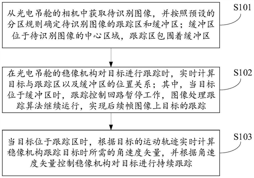
[0059] In the field of photoelectric reconnaissance and warning, cameras and their cameras are essential components. In the prior art, the camera and the camera without the motion feedback device can only observe the movement of the target within the field of view, while the camera and the camera mounted on the photoelectric pod can obtain a clear target under the movement of the image st...


PUM


Abstract

The invention provides a target tracking method, system and electronic equipment, and relates to the technical field of digital images. The method first acquires an image to be recognized from a camera of an optoelectronic pod, and determines the tracking area of ​​the image to be recognized according to a preset partition rule and buffer; when the image stabilization mechanism tracks the target, the positional relationship between the target and the tracking area and the buffer is calculated in real time; when the target is in the buffer, the tracking control loop is suspended, and the image processing and tracking algorithm continues to run to achieve subsequent The tracking of the target on the frame image; when the target is in the tracking area, the angular velocity vector required by the image stabilization mechanism to track the target is calculated in real time according to the motion trajectory of the target, and the image stabilization mechanism is controlled to continuously track the target according to the angular velocity vector. The method can control the image stabilization mechanism according to the real-time angular velocity when the image stabilization mechanism tracks the target and the angular velocity vector determined by the compensation angular velocity, and can eliminate the oscillation phenomenon of the pod during the target tracking process well.

Description

technical field [0001] The invention relates to the technical field of digital images, in particular to a target tracking method, system and electronic device. Background technique [0002] The static camera without motion feedback device can only observe the movement of the target within the field of view, while the camera mounted on the photoelectric pod can obtain a clear image of the target and track the moving target under the movement of the image stabilization mechanism, which realizes the real-time target. The effect of tracking largely depends on the motion control algorithm of the image stabilization mechanism. When performing the target tracking task, the sudden turning of the moving target will easily lead to the overshoot of the pod's image stabilization mechanism, and when the target reciprocates in a small range, the image stabilization mechanism will oscillate. SUMMARY OF THE INVENTION [0003] In order to solve the problem of motion overshoot and oscillat...

Claims


Application Information

Patent Timeline
Patent Type & Authority Patents(China)
IPC IPC(8): H04N5/232G06T7/20G06T7/70
CPCG06T7/20G06T7/70H04N23/695
Inventor 刘志何博侠
Owner 南京博蓝奇智能科技有限公司
Why Eureka
Try Eureka