Motor coil tin soldering charging plate positioning device
A technology of positioning device and loading plate, which is applied to auxiliary devices, welding equipment, metal processing equipment, etc., can solve the problems of inconvenient disassembly and achieve the effect of convenient operation and simple structure
- Summary
- Abstract
- Description
- Claims
- Application Information
AI Technical Summary
Problems solved by technology
Method used
Image
Examples
Embodiment 1
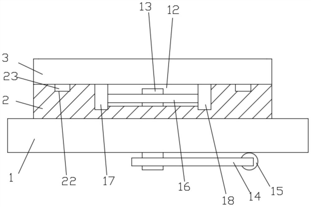
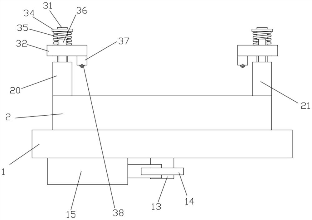
[0022] like Figure 1-2 Shown; A motor coil soldering loading plate positioning device, comprising:
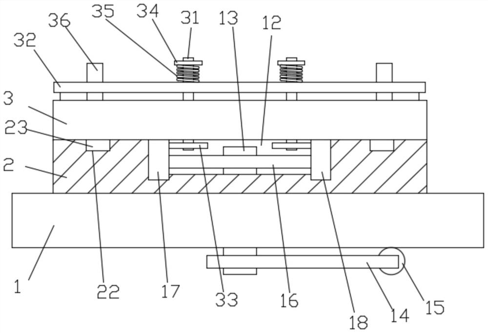
[0023] Welding platform 1, loading plate 2, splint 3;
[0024] The loading plate 2 is fixedly mounted on the welding platform 1, the loading plate 2 is provided with a horizontal channel 12, and a transmission shaft 13 is rotatably installed on the welding platform 1, and the upper end of the transmission shaft 13 is located in the horizontal groove In the road 12, the lower end is located at the lower part of the welding platform 1, the lower end of the transmission shaft 13 is fixed with a deflection rod 14, and the end of the deflection rod 14 is hinged on the cylinder 15, and the cylinder 15 is fixed at the lower part of the welding platform 1. A transmission gear 16 is fixedly installed on the upper end of the shaft 13, and a first rack 17 and a second rack 18 are slidably installed in the horizontal channel 12, and the first rack 17 and the second rack 18 are respective...
Embodiment 2
[0029] On the basis of Example 1, such as Figure 2-3 Shown; On each splint 3, limit mechanism is respectively installed, and described limit mechanism comprises limit shaft 31, limit plate 32, and described limit plate 32 is positioned at splint 3 tops, and described limit shaft 31 is rotatably installed on On the splint 3, the limit plate 32 is slidably installed on the limit shaft 31, the lower end of the limit shaft 31 is fixed with a driven gear 33, and the driven gear at the lower end of the limit shaft 31 on the first splint 20 33 is engaged on the second rack 18, and the driven gear 33 at the lower end of the limit shaft 31 on the second splint 21 is engaged with the first rack 17, and the upper end of the limit shaft 31 is threadedly connected with a lifting ring 34. The lifting ring 34 is located on the upper part of the limiting plate 32, and a pressing spring 35 is arranged between the lifting ring 34 and the limiting plate 32. When the splint 3 moves, it drives t...
PUM
 Abstract
Description
Claims
Application Information
 - R&D
- Intellectual Property
- Life Sciences
- Materials
- Tech Scout
- Unparalleled Data Quality
- Higher Quality Content
- 60% Fewer Hallucinations
Browse by: Latest US Patents, China's latest patents, Technical Efficacy Thesaurus, Application Domain, Technology Topic, Popular Technical Reports.
© 2025 PatSnap. All rights reserved.Legal|Privacy policy|Modern Slavery Act Transparency Statement|Sitemap|About US| Contact US: help@patsnap.com


