
Automatic mold locking force calibration device for injection molding machine

A technology of automatic calibration and clamping force, which is applied in the field of injection molding machines, can solve the problems of affecting processing efficiency, low adjustment and calibration efficiency, and low adjustment accuracy, and achieve the effects of improving stability, avoiding low efficiency, and increasing contact area

Pending Publication Date: 2021-07-16
HANGZHOU VOCATIONAL & TECHN COLLEGE
View PDF0 Cites 0 Cited by
  • Summary
  • Abstract
  • Description
  • Claims
  • Application Information

AI Technical Summary

Problems solved by technology

[0003] In order to solve the problems raised in the above-mentioned background technology, the object of the present invention is to provide an automatic clamping force calibration device for injection molding machines, which has the advantages of automatic calibration and solves the problem that the existing mode of clamping force calibration is manually Manually operate the panel to adjust the compression distance applied by the cylinder, the adjustment accuracy is low, and the adjustment and calibration efficiency is low, which is likely to affect the processing efficiency

Method used


Image

  • Automatic mold locking force calibration device for injection molding machine
  • Automatic mold locking force calibration device for injection molding machine
  • Automatic mold locking force calibration device for injection molding machine

Examples


Embodiment Construction

[0030] The technical solutions in the embodiments of the present invention will be clearly and completely described below with reference to the accompanying drawings in the embodiments of the present invention. Obviously, the described embodiments are only a part of the embodiments of the present invention, but not all of the embodiments. Based on the embodiments of the present invention, all other embodiments obtained by those of ordinary skill in the art without creative efforts shall fall within the protection scope of the present invention.

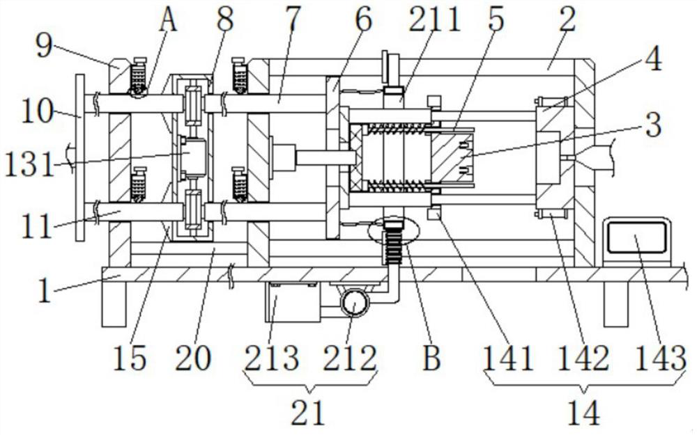
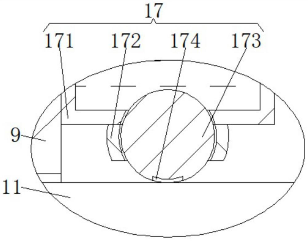
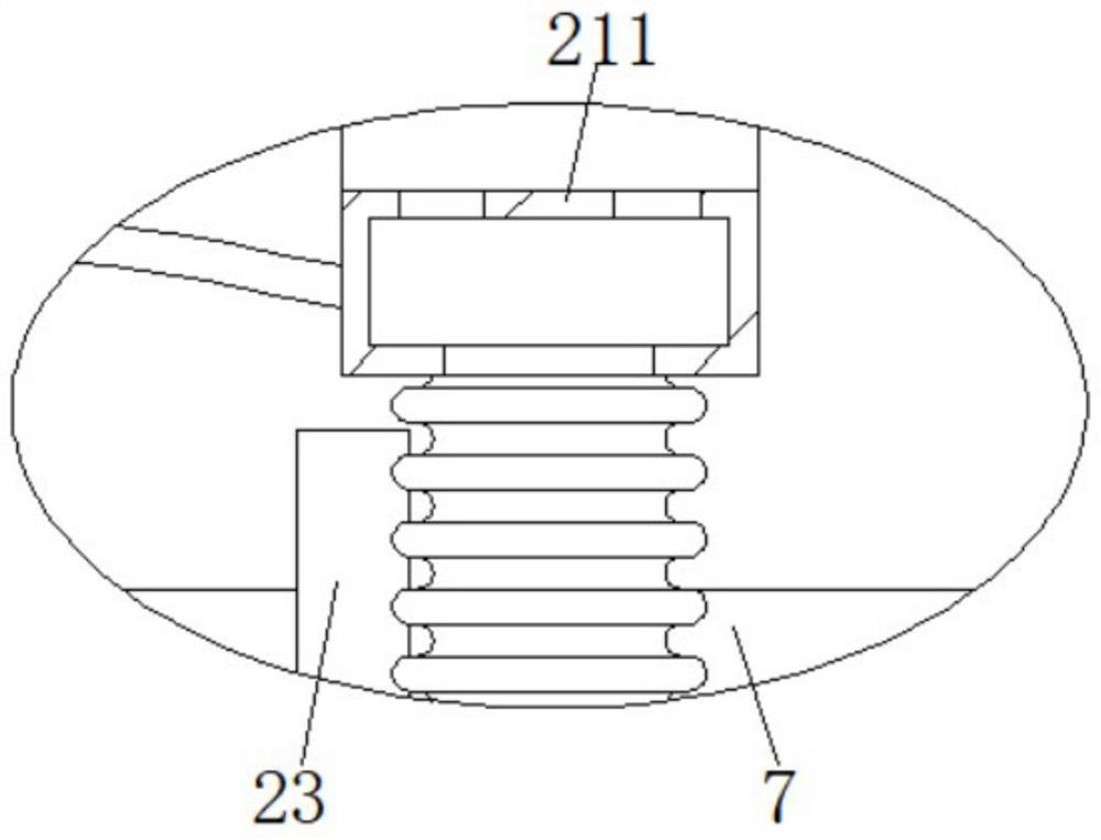
[0031] like Figure 1 to Figure 6 As shown, a clamping force automatic calibration device for injection molding machines provided by the present invention includes a bottom plate 1, a support frame 2 is fixedly connected to the top of the bottom plate 1, a movable mold 3 is arranged inside the support frame 2, and the support frame 2 The right side of the inner wall is fixedly connected with a fixed mold 4, the left side of the movabl...


PUM


Abstract

The invention discloses an automatic mold locking force calibration device for an injection molding machine. The automatic mold locking force calibration device comprises a bottom plate, the top of the bottom plate is fixedly connected with a support frame, the support frame is internally provided with a movable mold, the right side of the inner wall of the support frame is fixedly connected with a fixed mold, the left side of the movable mold is provided with an ejection device, and the left side of the movable mold is fixedly connected with a push plate through a connecting sleeve. The mold locking force between the movable mold and the fixed mold is detected by a detection mechanism, then the moving length of a second thread sleeve is limited by a transmission plate through a supporting plate, and finally the mold locking force is automatically adjusted by a transmission mechanism through a first thread sleeve and the push plate, so that the advantage of automatic calibration is achieved, and the problems that according to an existing mold locking force calibration mode, a panel is manually operated to adjust the pressing distance applied to an air cylinder, the adjustment accuracy is low, meanwhile, the adjustment calibration efficiency is low, and the machining efficiency is easily affected are solved.

Description

technical field [0001] The invention relates to the technical field of injection molding machines, in particular to an automatic mold clamping force calibration device for injection molding machines. Background technique [0002] The clamping force is the locking force applied to the mold by the injection machine. The existing mode of calibration of the clamping force is to adjust the clamping distance applied by the cylinder through the manual operation panel. The adjustment accuracy is low, and the adjustment and calibration efficiency is low. , easily affect the processing efficiency. Contents of the invention [0003] In order to solve the problems raised in the above-mentioned background technology, the object of the present invention is to provide an automatic clamping force calibration device for injection molding machines, which has the advantages of automatic calibration and solves the problem that the existing mode of clamping force calibration is manually The m...

Claims


Application Information

Patent Timeline
Patent Type & Authority Applications(China)
IPC IPC(8): B29C45/76B29C45/67B29C45/83B29C45/17
CPCB29C45/17B29C45/1753B29C45/67B29C45/7653B29C45/83B29C2945/76498B29C2945/76869
Inventor 胡美君
Owner HANGZHOU VOCATIONAL & TECHN COLLEGE
Learn More