
Sputum collecting device for pneumology department

A collection device and sputum technology, applied in the field of sputum collection devices used in respiratory department, can solve the problems of easily causing patients' health, rapid volatilization and integration, etc.

Pending Publication Date: 2021-07-23
颜文烦
View PDF0 Cites 2 Cited by
  • Summary
  • Abstract
  • Description
  • Claims
  • Application Information

AI Technical Summary

Problems solved by technology

[0005] In order to overcome the existing sputum basin, the bacteria in the sputum will quickly volatilize and merge into the air, which will easily cause the disadvantages of the patient's health. React Respiratory Sputum Collection Device

Method used


Image

  • Sputum collecting device for pneumology department
  • Sputum collecting device for pneumology department
  • Sputum collecting device for pneumology department

Examples


Embodiment 1

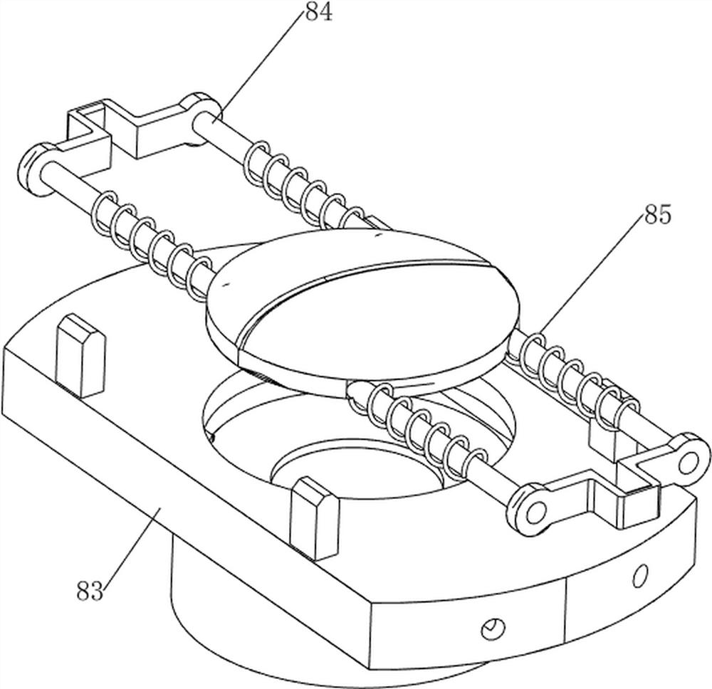
[0033] A device for collecting sputum in respiratory department, such as Figure 1-7 As shown, it includes a base 1, a collection box 2, a pedal 3, a first push rod 4, a first cover plate 5, a loading mechanism 6, a stretching mechanism 7 and a storage mechanism 8, and the base 1 is provided with a collection box 2 , the bottom of the collection box 2 is rotatably connected with a pedal 3, and the rear side of the collection box 2 is slidably connected with a first push rod 4, and the lower part of the first push rod 4 is rotatably connected with the foot pedal 3, and the rear side of the top of the collection box 2 The first cover plate 5 is rotatably connected, and the first cover plate 5 and the first push rod 4 are in contact with each other. The collection box 2 is provided with a loading mechanism 6, and the upper side of the collection box 2 is provided with a stretching mechanism 7. The loading mechanism 6 Place storage mechanism 8 on it.

[0034] The loading mechanis...

Embodiment 2

[0039] On the basis of Example 1, such as Figure 8-14 Shown, also includes flushing mechanism 9, and flushing mechanism 9 includes first fixed bar 91, spray pipe 92, water storage tank 93, bottle cap 94, rotating rod 96, slide bar 97, pressurization valve 98 and the second compression Spring 99, the left and right sides of collection box 2 inwall rear parts are all provided with the first fixed bar 91, and collection box 2 top is provided with spray pipe 92, and collection box 2 inner upper side is provided with water storage tank 93, and water storage box 93 and spray Tube 92 is connected, and the bottle cap 94 is threadedly connected to the front side of the water storage tank 93 tops, and the first fixed rod 91 is connected with a rotating rod 96 in a rotating manner. The pressurization valve 98 is slidably connected with a slide bar 97 between the pressurization valve 98, the slide bar 97 is connected with the rotary bar 96 front side in a rotational manner, the rear side...


PUM


Abstract

The invention relates to a collecting device, in particular to a sputum collecting device for the pneumology department. The technical problem to be solved is to provide the sputum collecting device for the pneumology department, which can play a role in environmental protection and avoid reaction with air. The sputum collecting device for the pneumology department comprises a base, a collecting box, a pedal, a first push rod and a first cover plate, wherein the collecting box is arranged on the base, the bottom of the collecting box is rotatably connected with the pedal, one side of the collecting box is slidably connected with the first push rod, the lower portion of the first push rod is rotatably connected with the pedal, the first cover plate is rotatably connected with one side of the top of the collecting box and is in contact fit with the first push rod. According to the device, through cooperation of a loading mechanism, a stretching mechanism and a storage mechanism, by stepping on the pedal, the first cover plate can be rotatably opened, and meanwhile, sputum can be collected and taken out conveniently.

Description

technical field [0001] The invention relates to a collection device, in particular to a sputum collection device for respiratory department. Background technique [0002] Medical equipment is the most basic element of medical treatment, scientific research, teaching, institutions, and clinical disciplines. It includes professional medical equipment and household medical equipment. In the respiratory department, in order to facilitate the storage of patient's sputum, it is necessary to use the sputum basin . [0003] Existing sputum basins are generally placed under the sickbed. When the patient needs to spit, the sputum basin needs to be taken out from under the bed for use. [0004] Moreover, when used in a high temperature environment in summer, the bacteria in the sputum will quickly volatilize and blend into the air in a high temperature environment. These bacteria are easily inhaled by the human body and cause harm to the health of the patient. Therefore, we propose a ...

Claims


Application Information

Patent Timeline
IPC IPC(8): A61J19/04
CPCA61J19/04
Inventor 颜文烦
Owner 颜文烦
Learn More