Blanking device for round hole of collecting pipe

The technology of collecting pipe and round hole is applied in the field of punching device for round hole of collecting pipe, which can solve the problems of low production efficiency, unnecessary use, and high labor intensity of workers, so as to improve production efficiency, reduce the number of loading and unloading, and reduce the The effect of labor intensity

Pending Publication Date: 2021-07-23
湖南东立智能科技有限公司
View PDF0 Cites 0 Cited by
  • Summary
  • Abstract
  • Description
  • Claims
  • Application Information

AI Technical Summary

Problems solved by technology

[0002] When using the traditional punching device to punch the header, only the circular holes at the same axial position can be punched. When the axial position of the circular hole changes, a different punching device is required. For punching, the operator cannot complete the processing of multiple round holes by loading and unloading materials in sequence; in addition, when the radial position of the round hole changes, it is also necessary to use a different punching device for punching, and, when When the diameter of the header changes, it is also necessary to replace different punching mechanisms for punching. The labor intensity of the workers is high and the production efficiency is low, so it needs to be improved.

Method used


Image

  • Blanking device for round hole of collecting pipe
  • Blanking device for round hole of collecting pipe
  • Blanking device for round hole of collecting pipe

Examples


Embodiment Construction

[0022] The present invention will be further described in detail below in conjunction with the accompanying drawings and specific embodiments.

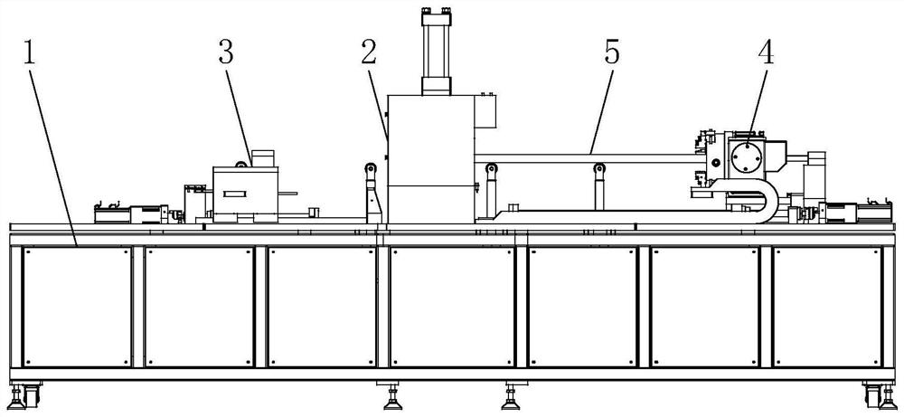
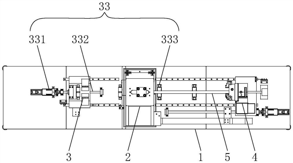
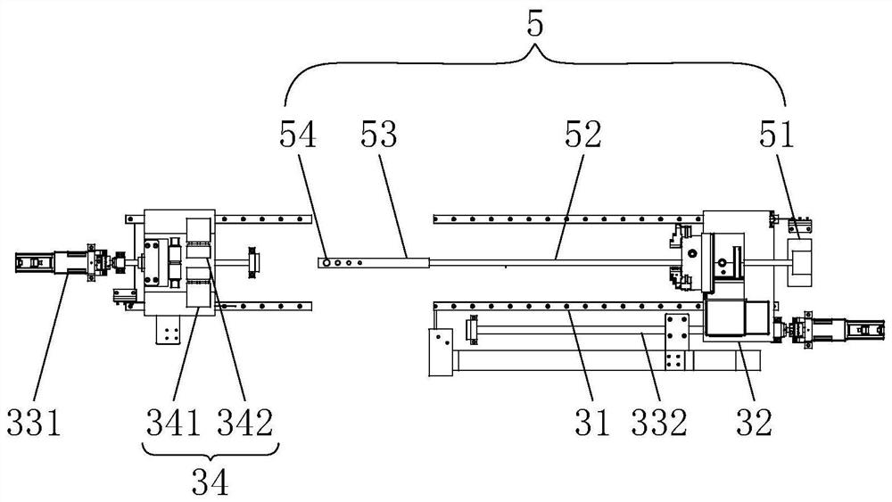
[0023] Figure 1 to Figure 5 It shows an embodiment of a punching device for a round hole of a collecting pipe according to the present invention, which includes a frame 1 on which a device for positioning the collecting pipe and punching a round hole for the collecting pipe is installed. The punching mechanism 2, the frame 1 is also equipped with an axial transfer mechanism 3 for adjusting the axial position of the collector at the two ends of the punching mechanism 2 to realize the punching of round holes at different stations, and the axial transfer mechanism The mechanism 3 is also equipped with a positioning chuck 4, and the frame 1 is also equipped with a core rod mechanism 5 pierced in the positioning chuck 4 for fixing collectors of different diameters. Through the cooperation between the punching mechanism 2 and the transfer...


PUM


Abstract

The invention relates to a blanking device for a round hole of a collecting pipe. The blanking device for the round hole of the collecting pipe comprises a rack, wherein a blanking mechanism used for positioning the collecting pipe and blanking the round hole of the collecting pipe is arranged on the rack; axial transferring mechanisms used for adjusting the axial position of the collecting pipe to achieve round hole blanking at different stations are further arranged at the positions, at the two ends of the blanking mechanism, of the rack; a positioning chuck is also arranged on each axial transferring mechanism; a core rod mechanism which is arranged in each positioning chuck in a penetrating manner and is used for fixing collecting pipes with different diameters is also arranged on the rack; through cooperation between the blanking mechanism and the transferring mechanisms, the collecting pipe can move in the axis direction, and the axial blanking station is changed; the collecting pipe can be rotated through the positioning chucks, so that the radial blanking station of the collecting pipe is adjustable; and the collecting pipes with different diameters can be fixed through the core rod mechanisms, and different blanking devices do not need to be used for blanking, so that the feeding and discharging frequency is reduced, the labor intensity of workers is relieved, and the production efficiency is improved.

Description

technical field [0001] The invention relates to the technical field of punching, in particular to a punching device for a round hole of a collector. Background technique [0002] When using the traditional punching device to punch the header, only the circular holes at the same axial position can be punched. When the axial position of the circular hole changes, different punching devices are required. For punching, the operator cannot complete the processing of multiple round holes by loading and unloading materials in sequence; in addition, when the radial position of the round hole changes, it is also necessary to use a different punching device for punching, and, when When the diameter of the collecting pipe changes, it is also necessary to replace different punching mechanisms for punching. The labor intensity of the workers is high and the production efficiency is low, so it needs to be improved. Contents of the invention [0003] The technical problem to be solved b...

Claims


Application Information

Patent Timeline
IPC IPC(8): B21D28/28B21D43/13B21D43/00
CPCB21D28/28B21D43/003B21D43/006B21D43/13
Inventor 焦韶勇李开泉黄文斌
Owner 湖南东立智能科技有限公司
Why Eureka
Try Eureka