Universal pneumatic self-locking clamping fixture

A general-purpose, self-locking clamp technology, which is applied in the direction of clamping, manufacturing tools, metal processing machinery parts, etc., can solve the problems that affect the normal processing quality of processed parts, cannot ensure the accurate positioning of processed parts, and do not set self-locking structures. , to achieve the effect of reducing investment in machine tools, convenient and quick disassembly, and strong versatility

Active Publication Date: 2018-10-12
宁波瑞立机械有限公司
View PDF11 Cites 0 Cited by
  • Summary
  • Abstract
  • Description
  • Claims
  • Application Information

AI Technical Summary

Problems solved by technology

However, on the one hand, this utility model does not have a self-locking structure, and it is easy to cause unstable or misaligned clamping positions during the processing of complex parts or parts with large cutting forces, which greatly affects the normal processing and processing quality of the processed parts, and is also easy to On the other hand, this utility model is not provided with diamond-shaped positioning pins on the positioning element, so the positioning of the processed parts cannot be guaranteed accurately, and the above-mentioned technical defects also exist

Method used


Image

  • Universal pneumatic self-locking clamping fixture
  • Universal pneumatic self-locking clamping fixture
  • Universal pneumatic self-locking clamping fixture

Examples


Embodiment 1

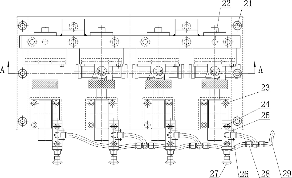
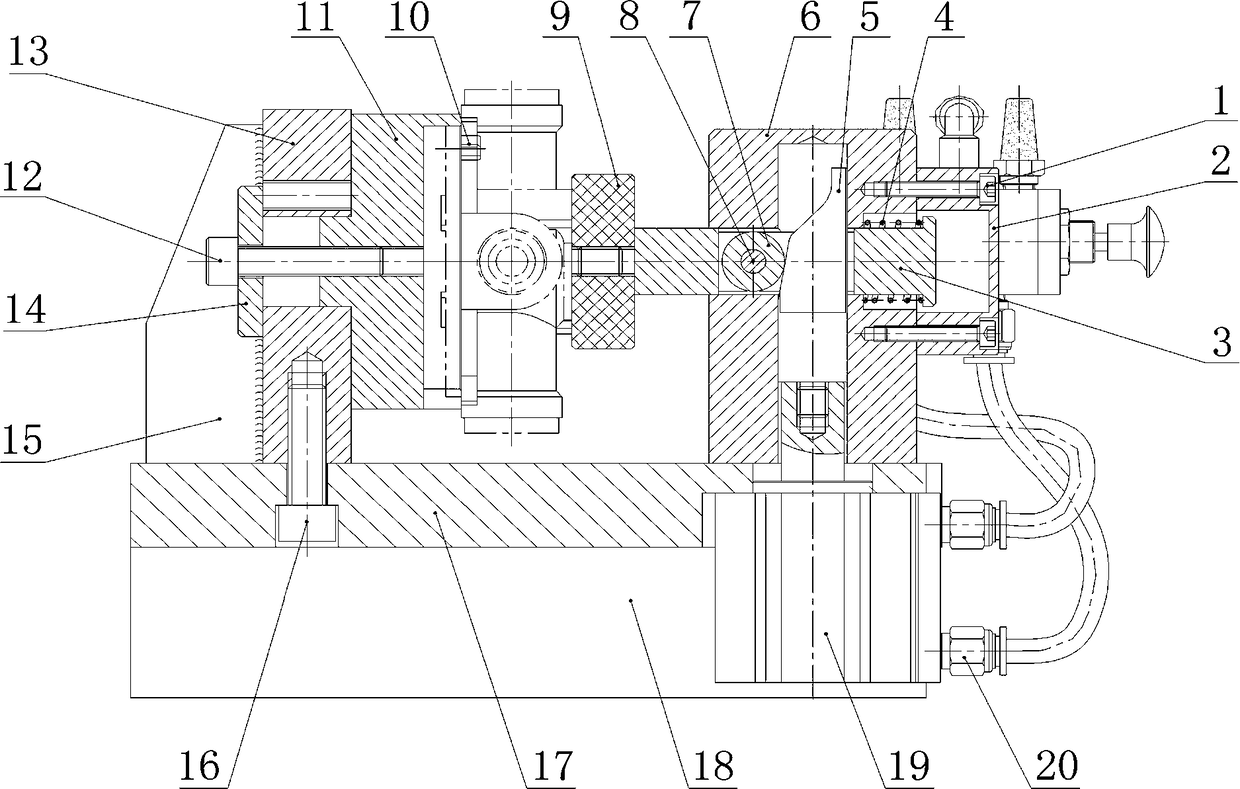
[0040] like Figure 1-3As shown, the general-purpose pneumatic self-locking clamping fixture includes a clamping device, and the clamping device adopts a wedge clamping mechanism, and the wedge clamping mechanism includes a wedge column 5 and a roller 7, and the wedge column 5 One end is provided with a piston rod mounting stud, and a roller 7 is arranged on the working inclined surface of the wedge column 5. Including a large lift angle at the front and a small lift angle at the rear, the self-locking angle of the clamping stroke is set to 5 degrees, including a power element, the power element adopts a cylinder, and the cylinder adopts a double-acting cylinder. Cylinder adopts Pu type cylinder 19, and Pu type cylinder 19 comprises piston rod, and one end of described piston rod is provided with internal thread interface, and described internal thread interface forms fastening connection with described piston rod installation stud on the wedge column 5 , including a guide bo...

Embodiment 2

[0049] The general-purpose pneumatic self-locking clamping fixture is similar to Embodiment 1, except that the self-locking angle of the clamping stroke is set to 8 degrees.

Embodiment 3

[0051] The general-purpose pneumatic self-locking clamping fixture is similar to Embodiment 1, except that the self-locking angle of the clamping stroke is set to 10 degrees.


PUM


Abstract

The invention relates to a universal type pneumatic self-locking clamping fixture. The fixture comprises a clamping device, wherein the clamping device adopts a wedge clamping mechanism, the wedge clamping mechanism comprises a wedge column (5) and a roller (7), a piston rod mounting double-screw bolt is arranged at one end of the wedge column (5), and the roller (7) is arranged on an inclined working surface of the wedge column (5). Compared with the prior art, the fixture has the beneficial effects as follows: clamping self-locking is controlled by the aid of a double-acting air cylinder, convenient and quick mounting and dismounting are realized, and the fixture is high in flexibility, can clamp a to-be-machined part firmly and realize quick self-locking in an instant and can also release the to-be-machined part in an instant after machining is completed, so that the mounting and dismounting efficiency is substantially improved; multiple clamping fixtures can be mounted on one working platform simultaneously, and thus multi-process or multi-station machining can be conducted at a time; the fixture is high in universality, particularly, the to-be-machined part is very convenient and quick to change, all that is required is to directly change a positioning base 11 and a rhombic pin 10, and accordingly, universal clamping and machining of different types of workpieces are realized.

Description

technical field [0001] The invention relates to a machine tool fixture, in particular to a general-purpose pneumatic self-locking clamping fixture. Background technique [0002] The Chinese utility model patent No. ZL201520485952.7 discloses a double-platen fixture, which includes a platen, a remote rod, a cylinder, a thrust rod, a clamp body, a supporting plate and a piston rod. The fixture is provided with two pressure plates, and the pressure plate is supported by two rockers of equal length, forming a parallelogram mechanism with the clamp body; two piston rods are installed at both ends of the cylinder, and the piston rod is connected to the pressure plate. The cylinder is connected with the clamp body through a thrust rod. When the piston rod of the cylinder moves up and down, the pressure plate will always be parallel to the horizontal base surface of the clamp body to complete the forward-tightening-loosen-backward action, which can be adjusted according to the workp...

Claims


Application Information

Patent Timeline
Patent Type & Authority Patents(China)
IPC IPC(8): B23Q3/08
CPCB23Q3/082
Inventor 陈建余永洪唐光林唐春艳
Owner 宁波瑞立机械有限公司
Why Eureka
Try Eureka