Full-automatic cable support forming equipment

A technology for cable brackets and forming equipment, which is applied in mechanical equipment, metal processing equipment, supports, etc., can solve the problems of particles being easily absorbed into the mouth by the staff, material beveled edges, and waste materials are not easy to collect, etc., so as to avoid the difficulty of plate movement, It is convenient for cutting work and avoids the effect of polluting the environment

Inactive Publication Date: 2021-07-23
浙江天控金属制造有限公司
View PDF7 Cites 0 Cited by
  • Summary
  • Abstract
  • Description
  • Claims
  • Application Information

AI Technical Summary

Problems solved by technology

[0003] At present, most of the cutting devices in the automatic cable support forming equipment are installed and fixed on the left side of the upper end of the base. When cutting, because there is no blocking device to fix the limit, the cut material is prone to beveled edges, which is harmful to production and production. It brings a lot of inconvenience to use, and the waste after cutting is not easy to collect, which is easy to pollute the surrounding environment, and the fine particles are easily absorbed into the mouth by the staff, which has an adverse effect on the health of the staff.

Method used


Image

  • Full-automatic cable support forming equipment
  • Full-automatic cable support forming equipment
  • Full-automatic cable support forming equipment

Examples


Embodiment Construction

[0024] The following will clearly and completely describe the technical solutions in the embodiments of the present invention in conjunction with the accompanying drawings in the embodiments of the present invention; obviously, the described embodiments are only part of the embodiments of the present invention, not all embodiments, based on The embodiments of the present invention and all other embodiments obtained by persons of ordinary skill in the art without making creative efforts belong to the protection scope of the present invention.

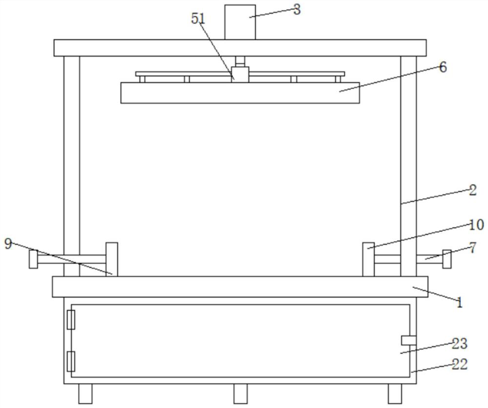
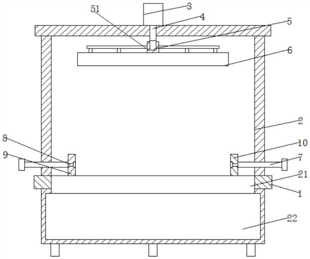
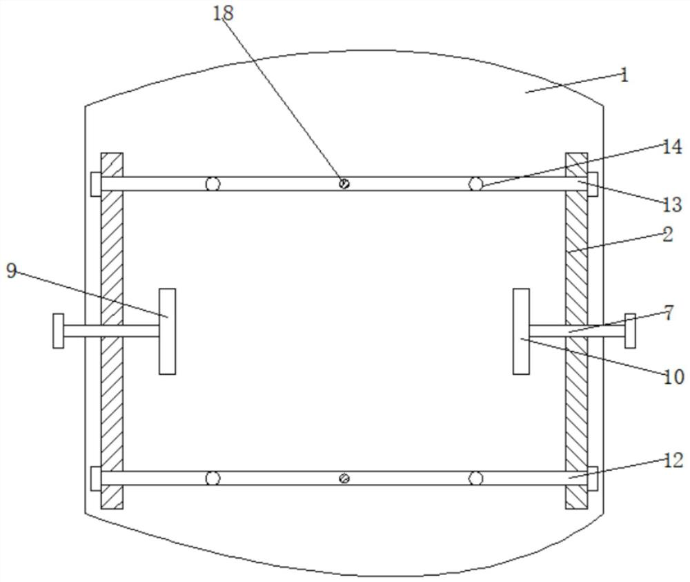
[0025] see Figure 1-5 , a fully automatic cable bracket forming equipment, including a base 1 and a ferrule 51, please refer to Figure 2-5 , the left side of the upper end of the base 1 is fixedly connected with the support frame 2, and the upper end of the support frame 2 is fixedly connected with the cylinder 3, the cylinder 3 is a SC series standard cylinder, the cylinder 3 is equipped with a control switch, the model is 4H210-08, a...


PUM


Abstract

The invention discloses full-automatic cable support forming equipment and belongs to the technical field of forming equipment. The full-automatic cable support forming equipment comprises a base and a clamping sleeve, wherein a supporting frame is fixedly connected with the left side of the upper end of the base; an air cylinder is fixedly connected with the upper end of the supporting frame; a cutting knife is fixedly connected with the lower end of the clamping sleeve; rotating rods are rotationally connected with the left and right sides of the lower end of the supporting frame through threads correspondingly; a rotating shaft is rotationally connected with one end of each rotating rod; and a left baffle plate and a right baffle plate are rotationally connected with the rotating shafts correspondingly. Through the connection among the supporting frame, the rotating rods and the rotating shafts, the left baffle plate and the right baffle plate can be conveniently limited and fixed, and then different-width materials can be conveniently limited and fixed; the phenomenon that the edge cutting position inclines due to the sliding of a material plate in the cutting process can be avoided; and meanwhile, through the arrangement of a front pressing plate, a rear pressing plate, positioning rods, a front buffering plate, a rear buffering plate, springs, T-shaped shafts, limiting rods and transverse rods, the front and rear parts of the plate can be limited, the plate can be prevented from being separated from the surface of the upper end of the base in the cutting process, and the cutting work can be facilitated.

Description

technical field [0001] The invention relates to the technical field of forming equipment, and more specifically, relates to a fully automatic cable support forming equipment. Background technique [0002] Cables are laid in cable trenches and tunnels, and are generally fixed with brackets. Commonly used brackets include angle steel brackets and fabricated brackets. There are 7 different models and specifications of angle steel brackets used in cable trenches. The vertical distance between support layers is 300mm for installing 35kV cables; 120mm is for installing control cables. [0003] At present, most of the cutting devices in the automatic cable support forming equipment are installed and fixed on the left side of the upper end of the base. When cutting, because there is no blocking device to fix the limit, the cut material is prone to beveled edges, which is harmful to production and production. Use all brings a lot of inconvenience, and the waste material after cutt...

Claims


Application Information

Patent Timeline
Patent Type & Authority Applications(China)
IPC IPC(8): B23D79/00B23Q3/06B23Q11/00F16F15/067
CPCB23D79/00B23Q3/06B23Q11/0032F16F15/067
Inventor 叶兆升
Owner 浙江天控金属制造有限公司
Why Eureka
Try Eureka