Fireproof intelligent lock supporting emergency escape

An intelligent lock and emergency technology, applied in the field of intelligent locks, can solve problems such as emergency keys not being carried around, outdoor rescuers cannot enter quickly, and motor components 300 cannot receive action signals, etc., achieving the effect of novel structure and avoiding loss of life and property.

Pending Publication Date: 2021-07-23
广西贵港和乐门业有限公司
View PDF0 Cites 0 Cited by
  • Summary
  • Abstract
  • Description
  • Claims
  • Application Information

AI Technical Summary

Problems solved by technology

[0003] However, the semi-automatic smart lock in the prior art only has the function of quickly unlocking the indoor handle and the escape function when encountering a sudden fire. In the case of quick escape in a short period of time, or when there is no one in the room, outdoor rescuers cannot quickly enter; although the smart lock mandatory technical specification requires that the smart lock must have the function of emergency key unlocking, in general, the emergency key is not to be carried with you. At the same time, if the high temperature causes the electronic control components to fail, even if the legal owner arrives at the scene, there is nothing to help. Therefore, a smart lock that can support the outdoor quick opening of the door through mechanical linkage in the event of a fire is particularly important.
[0004] The deficiencies of existing smart locks in response to fires: such as figure 1 and 2 As shown, when a fire occurs indoors, the high temperature makes the electronic control part of the smart lock invalid, the motor assembly 300 cannot receive the action signal, the motor push rod 500 does not move, the thimble 200 does not move, and the thimble 200 cannot be inserted into the side opening of the square steel connecting shaft 400. In the slot hole, the outdoor handle cannot drive the square steel connecting shaft 400 to rotate through the rotating shaft 100, and the outdoor handle cannot open the door

Method used


Image

  • Fireproof intelligent lock supporting emergency escape
  • Fireproof intelligent lock supporting emergency escape
  • Fireproof intelligent lock supporting emergency escape

Examples


Embodiment Construction

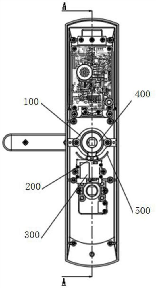
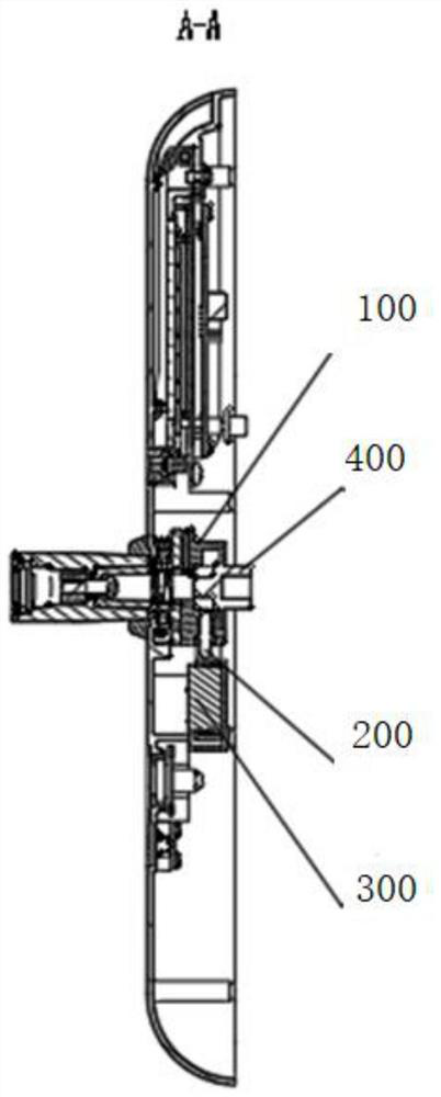
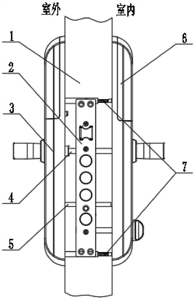
[0030] like Figure 3-Figure 14 As shown, a fireproof intelligent lock supporting emergency escape, including: a lock body 2, the lock body 2 is assembled on the side of the door body 1;

[0031] like Figure 3-6 As shown, the outer panel part 3, the outer panel part 3 is assembled on the outside of the door body 1; the inner panel part 6, the inner panel part 6 is assembled on the inner side of the door body 1; the outer panel part 3 and the inner panel part 6 are assembled by The installation accessories 7 (connecting pipes and screws) are fixed on the outdoor and indoor sides of the door body 1, and the motion transmission is carried out through the square steel 4 and the transmission shaft 5. The outer panel part 3 is provided with a clutch module, and the inner panel part 6 is provided with a temperature sensing mechanical part. The two ends of the transmission shaft 5 are respectively connected with the clutch module and the temperature sensing mechanical part, and the ...


PUM


Abstract

The invention discloses a fireproof intelligent lock supporting emergency escape, and relates to the technical field of intelligent locks. The fireproof intelligent lock comprises a lock body, an outer panel part and an inner panel part, wherein the lock body is assembled on the side surface of a door body; the outer panel part is assembled on the outdoor side of the door body; the inner panel part is assembled on the indoor side of the door body; the outer panel part and the inner panel part perform motion transmission through square steel and a transmission shaft; and a clutch module is arranged in the outer panel part, a temperature sensing mechanical part is arranged in the inner panel part, the two ends of the transmission shaft are connected with the clutch module and the temperature sensing mechanical part respectively, the transmission shaft is driven to rotate through the temperature sensing mechanical part, and then the clutch module is driven to achieve unlocking. The intelligent lock is novel in structure, and the personal and property loss caused by the fact that a door cannot be effectively and rapidly opened is fundamentally avoided when the intelligent lock is applied to emergency situations such as fire disasters or explosions.

Description

technical field [0001] The invention relates to the technical field of intelligent locks, in particular to a fire-proof intelligent lock supporting emergency escape. Background technique [0002] Fire accidents occur frequently, and it is often reported that when a fire breaks out in a certain community, the trapped people cannot escape or the rescuers cannot quickly enter the fire scene to rescue accidents, causing greater casualties or property losses. With the continuous injection of high-tech to traditional locks , so that the security function of the lock has been fully extended and expanded, and its status and function cannot be replaced by any mechanical lock. [0003] However, the semi-automatic smart lock in the prior art only has the function of quickly unlocking the indoor handle and the escape function when encountering a sudden fire. In the case of quick escape in a short period of time, or when there is no one in the room, outdoor rescuers cannot quickly enter...

Claims


Application Information

Patent Timeline
Patent Type & Authority Applications(China)
IPC IPC(8): E05B65/10E05B3/00E05B9/00E05B15/00E05B17/22E05B47/00
CPCE05B3/00E05B9/002E05B15/00E05B17/22E05B47/0001E05B47/0673E05B65/104
Inventor 刘保全汤小飞
Owner 广西贵港和乐门业有限公司
Why Eureka
Try Eureka