A high-power power turbine rotor axial force adjustment structure

A power turbine and adjusting structure technology, which is applied to engine components, machines/engines, non-variable engines, etc., can solve problems such as endangering the normal operation of bearings, and achieve high reliability effects

Active Publication Date: 2022-07-01
AECC HUNAN AVIATION POWERPLANT RES INST
View PDF0 Cites 0 Cited by
  • Summary
  • Abstract
  • Description
  • Claims
  • Application Information

AI Technical Summary

Problems solved by technology

[0003] The present invention provides a high-power power turbine rotor axial force adjustment structure to solve the technical problem that the existing high-power power turbine rotor seriously endangers the normal operation of the bearing due to the large axial force

Method used


Image

  • A high-power power turbine rotor axial force adjustment structure
  • A high-power power turbine rotor axial force adjustment structure
  • A high-power power turbine rotor axial force adjustment structure

Examples


Embodiment Construction

[0024] It should be noted that the embodiments in the present application and the features of the embodiments may be combined with each other in the case of no conflict. The present invention will be described in detail below with reference to the accompanying drawings and in conjunction with the embodiments.

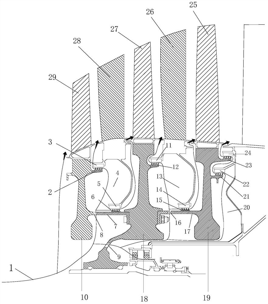
[0025] refer to figure 1 , the preferred embodiment of the present invention provides a high-power power turbine rotor axial force adjustment structure, between the adjacent disks of the power turbine and the rear side of the final disk are provided with air flow paths 1-connected and used to make the rearward axial force of the power turbine disk into a forward offsetting part of the aerodynamic force of the rotor blades, thereby reducing the axial force of the entire power turbine rotor.

[0026] Specifically, two seals with a certain radius difference are arranged between adjacent discs, and two bushings are respectively fitted with the two seals in a sealing manner...


PUM


Abstract

The invention discloses a high-power level power turbine rotor axial force adjustment structure. Between adjacent discs of the power turbine and at the rear side of the final stage disc are provided with an air flow path for communication with an air flow path. The rearward axial force of the power turbine disk becomes a boost regulating cavity that cancels a part of the rotor blade aerodynamic force forward, thereby reducing the axial force of the entire power turbine rotor. The invention adopts a segmented adjustment method, and allocates the adjustment margin of the axial force of the entire engine power turbine rotor to the adjustment chambers between the turbine disks of each stage and the rear side of the last-stage disk, and the adjustment chambers are arranged in sequence, so that the adjustment scheme has The high reliability ensures that the axial force of the power turbine rotor is reduced to the range that the bearing can bear, and solves the problem of excessive axial force of the power turbine rotor of the high power level.

Description

technical field [0001] The present invention relates to the field of power turbines, and in particular, to a structure for adjusting the axial force of a power turbine rotor with a high power level. Background technique [0002] Aero-type turboprop and turboshaft engines mainly rely on the power turbine for power output. The engine air system is mainly responsible for the cooling of the power turbine disk cavity, the sealing between stages and the balance adjustment of the axial force. The axial force of the power turbine rotor is mainly driven by the aerodynamic force of the turbine blades. When the power level of the power turbine is large, the axial force of the entire power turbine rotor is also large, and the bearing will be difficult to bear the load of the axial force of the rotor, which seriously endangers the normal operation of the bearing. SUMMARY OF THE INVENTION [0003] The present invention provides a high-power level power turbine rotor axial force adjustme...

Claims


Application Information

Patent Timeline
Patent Type & Authority Patents(China)
IPC IPC(8): F01D1/02F01D11/00F01D11/02F01D5/06F01D5/02
CPCF01D1/02F01D11/005F01D11/02F01D5/06F01D5/027
Inventor 张远森周志翔陈竞炜白忠恺
Owner AECC HUNAN AVIATION POWERPLANT RES INST
Why Eureka
Try Eureka