Automatic survey probe replacing device and method thereof

A technology of automatic replacement and stylus, applied in the field of precision measurement, can solve problems such as reports or literature that have not yet been found, and achieve the effect of solving the problem of large axial magnetic force, reducing the effect of axial magnetic force, and facilitating access

Inactive Publication Date: 2008-04-02
XIAN TECHNOLOGICAL UNIV
View PDF11 Cites 9 Cited by
  • Summary
  • Abstract
  • Description
  • Claims
  • Application Information

AI Technical Summary

Problems solved by technology

[0009] The project team of this invention has searched domestic and foreign patent documents and published journal papers, and has not found any reports or documents closely related to the present invention.

Method used


Image

  • Automatic survey probe replacing device and method thereof
  • Automatic survey probe replacing device and method thereof
  • Automatic survey probe replacing device and method thereof

Examples


Embodiment 1

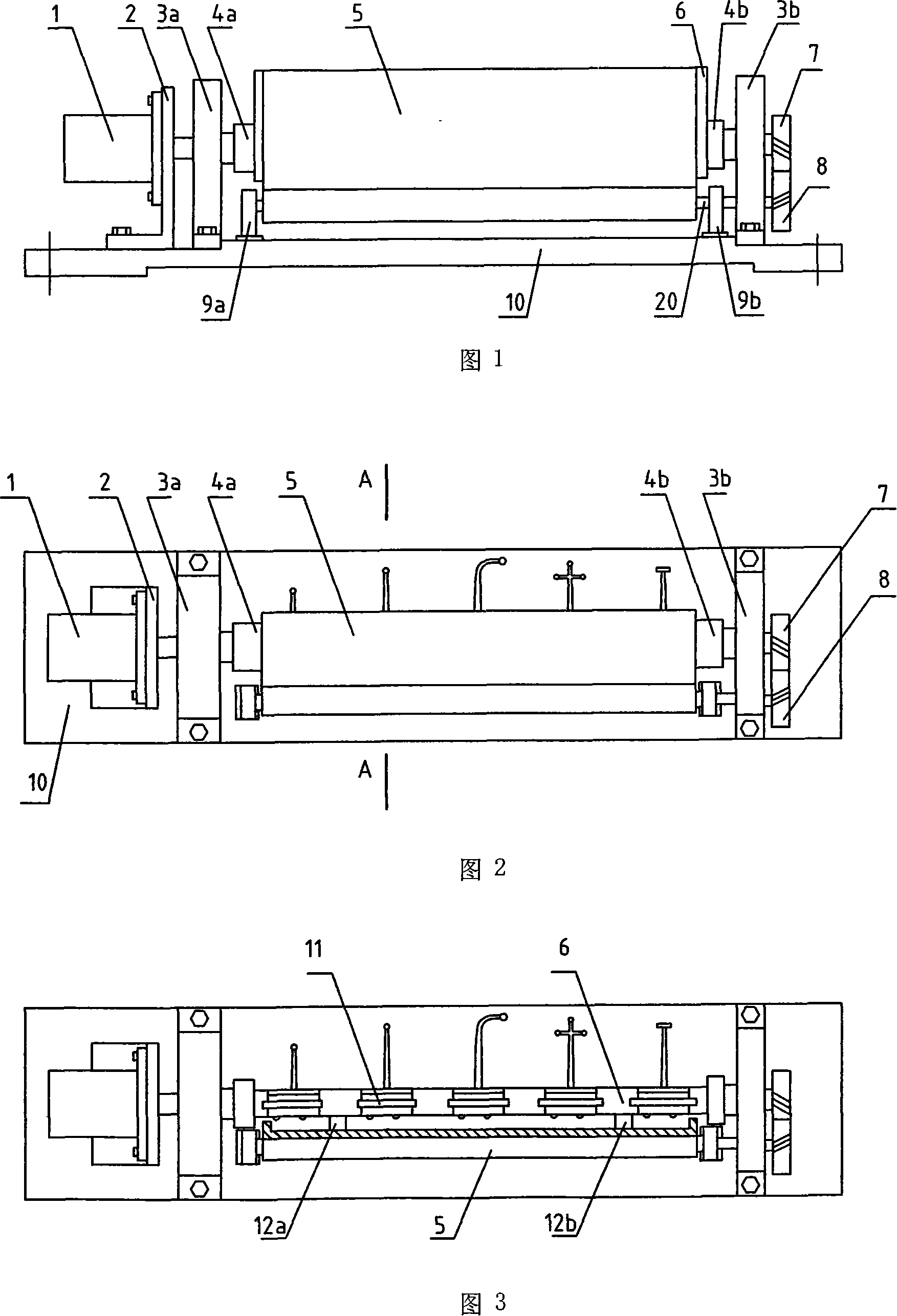
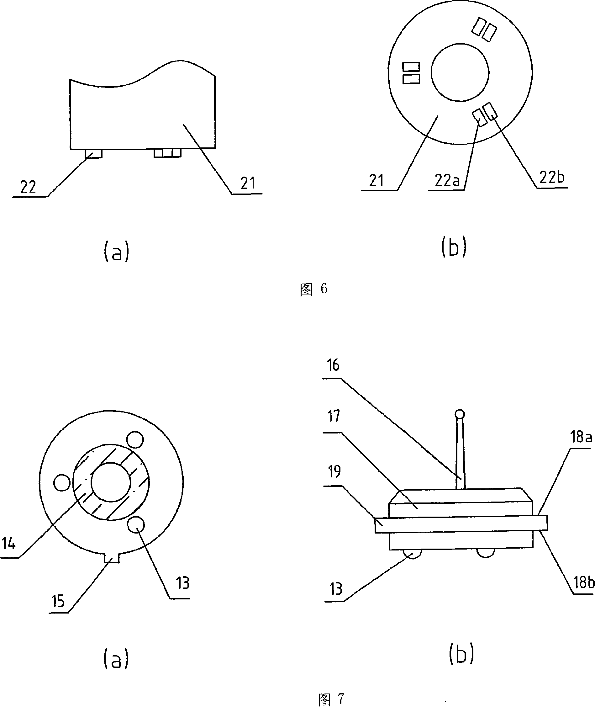
[0041] Embodiment 1: As shown in FIG. 1, the present invention is an automatic stylus replacement device, including a stylus 21, a stylus module 11, a stylus module storage rack 6, a protective cover 5, a control computer, and a stylus module. There is a positioning ball 13 at the bottom, which is equipped with a permanent magnet 14, which is related to the access control of the measuring machine stylus. The specially designed stylus storage rack is installed on the working table of the coordinate measuring machine through the bottom plate 10, which can be selected according to the measurement requirements. Placed at a suitable position on the work surface, the stylus 16 is fixedly mounted on the stylus module 11. In order to facilitate the replacement of the stylus 16, the stylus 16 is installed on the standard module board 17, which can be connected by thread or The standard stylus module 11 is made by directly soldering it on the module board, see Fig. 6b for details. In or...

Embodiment 2

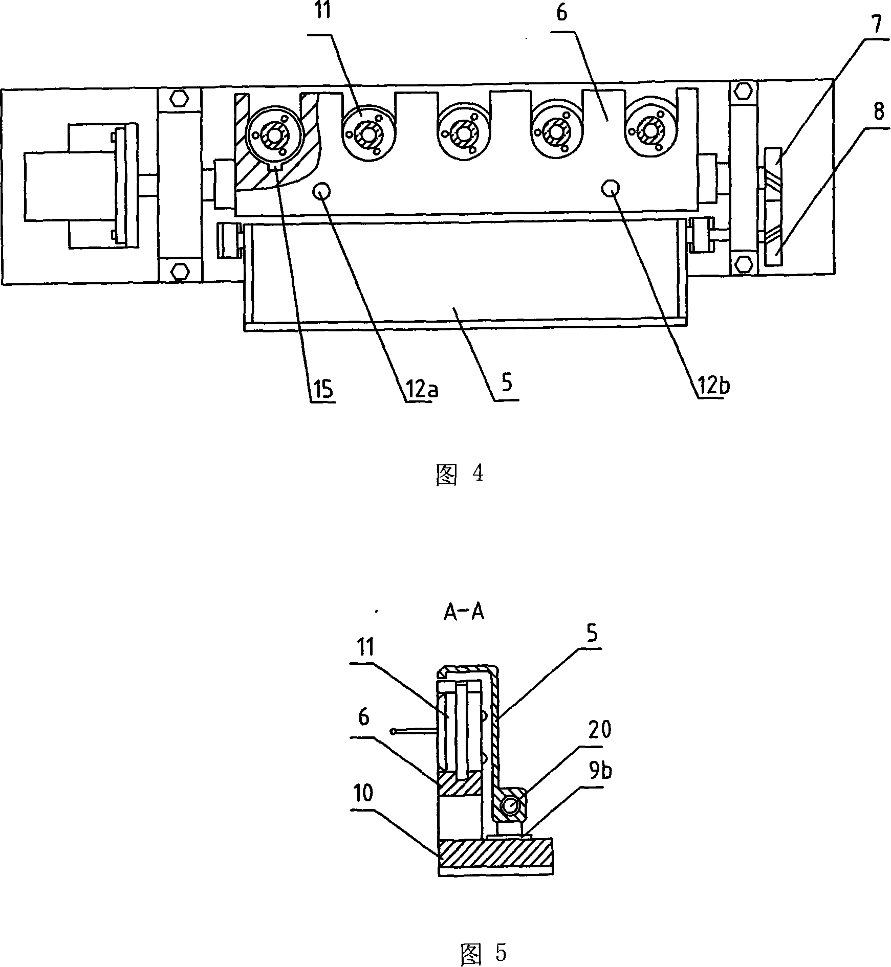
[0045] Embodiment 2: Referring to Fig. 3, the overall device is the same as that of Embodiment 1. The stylus module is a stylus module 11 with styli of different sizes and specifications fixedly installed, and the diameters of the outer circular bosses are also different. See Fig. 4. The diameters of the U-shaped grooves of the stylus module are also different and correspond to each other one by one. Since a plurality of stylus modules can be placed on the storage rack 6, it is stipulated that for a stylus of each specification, the stylus module can only be installed at the position of a U-shaped support seat of the storage rack, and multiple stylus modules are not allowed. The case where the needle module can be mounted on a U-shaped support. Otherwise, the measurement equipment will be wrongly installed with a stylus that does not meet the requirements, making the measurement impossible or the measurement result wrong.

[0046] FIG. 6 is a detailed structural diagram of th...

Embodiment 3

[0048] Embodiment 3: Referring to Fig. 3, the overall device is the same as that of Embodiment 1, in which the stylus module storage rack 6 is provided with 5 U-shaped grooves, which are respectively placed into the long and short spherical stylus and elbow. Stylus stylus, star stylus, disc stylus are commonly used types of stylus.


PUM


Abstract

The invention provides a point gauge automatic replace device and a point gauge replace method. When a point gauge module is placed on a point gauge storage shelf, the storage shelf is driven by a motor to rotate at a small angle with a self-shaft, thereby reducing an axial magnetic force, and solving a technical problem that a probe bears a large axial magnetic force when the point gauge module is disassembled from the probe. The point gauge storage shelf is specially designed, one end of the point gauge module storage shelf which is connected with a driving shaft is connected with a control motor shaft, while the other end is connected with gears, two gears are meshed and respectively connected with the driving shaft and a driven shaft, a motor drives the two shafts to be reversely turned, thereby achieving that the storage shelf and a protective cover automatically open and automatically return to a vertical position, and the cover is closed. The point gauge replace process of the invention is stably run, steps and programs are simpler and easier, a device structure is simplified, complicated control is not required, the probe can be well protected, and a service life of the probe is effectively improved. The invention can be widely applied to precision measurement technical field, such as a coordinate measuring machine, etc.

Description

technical field [0001] The invention belongs to the technical field of precision measurement, relates to a three-coordinate measuring machine, and mainly relates to a stylus replacement device and method of the three-coordinate measuring machine, specifically a novel automatic stylus replacement device and a stylus automatic replacement method. Background technique [0002] With the rapid development of precision measurement technology, coordinate measuring equipment is increasingly used in automated production lines and product testing. For example, coordinate measuring machines are used to detect and inspect products with complex structures such as gears, blades, crankshafts, and cams. Coordinate measuring machines are constantly updated to meet the needs of industrial production, which makes people's demand for testing equipment with new functions, high precision, and high automation continue to increase. [0003] When using the CMM to measure some complex parts with oute...

Claims


Application Information

Patent Timeline
Patent Type & Authority Applications(China)
IPC IPC(8): G01B5/012G01B7/012
Inventor 强怀博王建华李平劳奇成刘波吴琼卢春霞王晓丽
Owner XIAN TECHNOLOGICAL UNIV
Why Eureka
Try Eureka