Monitoring device based on big data network

A monitoring device and big data technology, which is applied in the direction of supporting machines, mechanical equipment, machine platforms/supports, etc., can solve the problems of limited monitoring range, fixed structure, inconvenient maintenance and repair of staff, etc., to expand the monitoring range and facilitate maintenance and maintenance, easy to adjust the effect

Pending Publication Date: 2021-07-23
JIYANG COLLEGE OF ZHEJIANG A & F UNIV
View PDF5 Cites 4 Cited by
  • Summary
  • Abstract
  • Description
  • Claims
  • Application Information

AI Technical Summary

Problems solved by technology

However, the existing monitoring devices usually have a fixed structure and cannot flexibly adjust the monito

Method used


Image

  • Monitoring device based on big data network
  • Monitoring device based on big data network
  • Monitoring device based on big data network

Examples


Embodiment 1

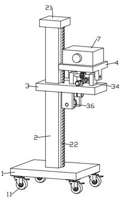
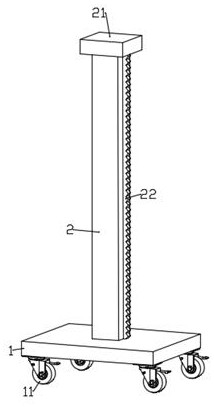
[0026] see Figure 1~6 , a monitoring device based on a big data network, comprising a base 1, a lifting plate 3 and a mounting plate 4, the upper end surface of the base 1 is fixedly installed with a vertical guide rod 2, and one end of the lifting plate 3 is provided with a Through the chute 31, the lifting plate 3 is slidingly connected with the guide rod 2 through the chute 31, the bottom of the lifting plate 3 is provided with a lifting and sliding transmission mechanism, and the upper end surface of the lifting plate 3 is far away from the upper end of the chute 31. A mounting plate 4 is arranged on the side, an angle adjustment mechanism is arranged between the mounting plate 4 and the lifting plate 3, a monitor 7 is fixedly installed on the upper end surface of the mounting plate 4, and a camera is arranged on the front side of the monitor 7 71.

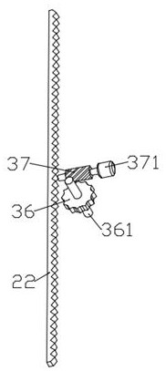
[0027] The lifting and sliding transmission mechanism includes a rack 22, a first worm wheel 36, a first rotating shaft 36...

Embodiment 2

[0031] see Figure 1~6 , a monitoring device based on a big data network. On the basis of Embodiment 1, a pair of first mounting brackets 32 are arranged laterally on the bottom of the lifting plate 3, and the first worm 37 is rotatably mounted on a pair of first mounting brackets. Between the frames 32, a pair of second mounting frames 33 are arranged longitudinally on the bottom of the lifting plate 3, and the first rotating shaft 361 is rotatably installed between the pair of second mounting frames 33. The upper end surface of the lifting plate 3 A pair of third mounting brackets 35 are longitudinally arranged, and the second worm 6 is rotatably mounted between the pair of third mounting brackets 35. A limiting plate 21 is arranged on the top of the guide rod 2 to limit the height of the lifting plate 3. The height of the rise, the bottom of the base 1 is equipped with a plurality of symmetrically arranged universal wheels 11, which is convenient for a monitoring device bas...


PUM


Abstract

The invention discloses a monitoring device based on a big data network. The monitoring device comprises a base, a lifting plate and a mounting plate, wherein a vertically arranged guide rod is fixedly mounted on the upper end surface of the base; a through sliding groove is formed in one end of the lifting plate; the lifting plate is in sliding connection with the guide rod through the sliding groove; a lifting sliding transmission mechanism is arranged at the bottom of the lifting plate; the mounting plate is arranged on the upper side of one end, far away from the sliding groove, of the upper end surface of the lifting plate; an angle adjusting mechanism is arranged between the mounting plate and the lifting plate; a monitor is fixedly mounted on the upper end surface of the mounting plate; and a camera is arranged on the front side of the monitor. According to the monitoring device, the lifting sliding transmission mechanism is arranged, so that the height of the monitor can be adjusted, the monitor can conveniently carry out camera monitoring at different heights, and a worker can conveniently maintain and overhaul the monitor; and the angle adjusting mechanism is arranged, so that the inclination angle of the monitor can be conveniently adjusted, and the monitoring range of the monitor is expanded.

Description

technical field [0001] The invention relates to the technical field of monitoring, in particular to a monitoring device based on a big data network. Background technique [0002] Big data, a term in the IT industry, refers to a collection of data that cannot be captured, managed, and processed by conventional software tools within a certain period of time. It requires a new processing model to have stronger decision-making power, insights and process optimization capabilities. Massive, high growth rate and diverse information assets. [0003] Commonly used monitoring devices are usually connected to big data networks to monitor, analyze and process various scenarios. However, the existing monitoring devices usually have a fixed structure and cannot flexibly adjust the monitoring height and angle, resulting in a limited monitoring range, and it is not convenient for staff to maintain and overhaul. Contents of the invention [0004] The purpose of the present invention is ...

Claims


Application Information

Patent Timeline
IPC IPC(8): F16M11/04F16M11/10F16M11/18F16M11/42
CPCF16M11/42F16M11/04F16M11/18F16M11/10F16M11/046
Inventor 刘福泉余涛
Owner JIYANG COLLEGE OF ZHEJIANG A & F UNIV
Why Eureka
Try Eureka