
RRU remote system

A network management system and one-way technology, applied in the field of RRU remote system, can solve the problems of limited base station antenna height, higher and higher signal quality requirements, and insufficient coverage, so as to reduce the difficulty of property coordination and engineering construction, and save equipment Cost and power consumption cost, the effect of simple construction method

Inactive Publication Date: 2021-07-23
深圳林诺科技有限公司
View PDF0 Cites 3 Cited by
  • Summary
  • Abstract
  • Description
  • Claims
  • Application Information

AI Technical Summary

Problems solved by technology

[0003] With the development of 5G technology and the rapid increase in the number and user density of large buildings in cities, this poses a great challenge to the network coverage of mobile communications. Due to the current signal shielding effect of large buildings on mobile communications Strong, especially in the underground floors and elevators, it is easy to generate signal blind spots, while high floors are limited by the height of the base station antenna, which is also prone to insufficient coverage and signal blind spots
For the middle floor, it is easy to produce the ping-pong effect caused by the mutual interference of base station signals in different cells, resulting in frequent switching of mobile phones or even dropped calls
At the same time, due to the high density of users in large buildings, it is easy to cause congestion, and the requirements for signal quality of users are getting higher and higher.
[0004] The current situation is that 2G networks, 3G networks and 4G networks will coexist for a long period of time in the mobile communication network. Therefore, there are resources to completely abandon the existing network and build a new 5G network to meet the demand. Wasteful, costly and unattainable

Method used


Image

  • RRU remote system
  • RRU remote system
  • RRU remote system

Examples


Embodiment Construction

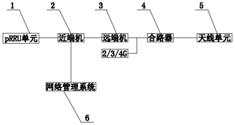
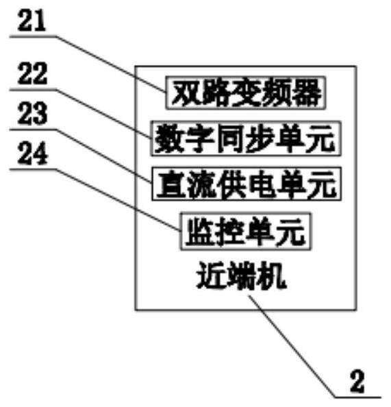
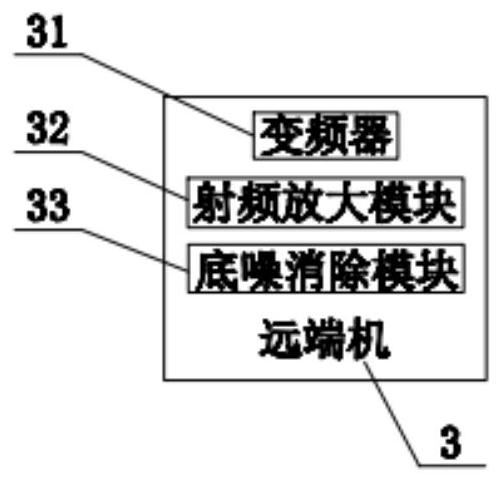
[0026] see Figure 1-Figure 4 As shown, the technical solution adopted in this specific embodiment is: a RRU remote system, which includes a pRRU unit 1, a near-end unit 2, a remote unit 3, a combiner 4, an antenna unit 5 and a network management system 6, The signal input end of the described near-end machine 2 is connected to the signal output end of the pRRU unit 1, and the signal output end of the described near-end machine 2 is connected with the signal input end of the far-end machine 3, so the combiner 4 The signal input terminal includes two signal input terminals, one signal input terminal of the combiner 4 is connected to the signal output terminal of the remote machine 3, and the other signal input terminal of the combiner 4 is connected to a 2G, 3G or 4G signal, said The signal input end of the antenna unit 5 is connected to the signal output end of the combiner 4, and the network management system 6 is connected to the near-end machine 2;

[0027] The near-end ma...


PUM


Abstract

The invention discloses a remote radio unit (RRU) remote system and relates to a signal coverage system. The system comprises a pRRU unit, a near-end machine, a far-end machine, a combiner, an antenna unit and a network management system, wherein a signal input end of the near-end machine is connected with a signal output end of the pRRU unit, a signal output end of the near-end machine is connected with a signal input end of the far-end machine, the signal input end of the combiner comprises two paths of signal input ends, one path of signal input end of the combiner is connected with the signal output end of the far-end machine, the other path of signal input end of the combiner is connected with 2G, 3G or 4G signals, the signal input end of the antenna unit is connected with the signal output end of the combiner, and the signal input end of the antenna unit is connected with the signal output end of the far-end machine. The network management system is connected with the near-end machine, and in the original 2G3G4G signal coverage scene, when 5G coverage is established, signal coverage is completed through a PRU remote system after only one small base station information source is established.

Description

technical field [0001] The present invention relates to the technical field of communication, in particular to an RRU remote system. Background technique [0002] In the mobile communication network, the RRU remote system, as the extension and supplement of the base station in the coverage network, can improve the signal quality and solve the problem of call drop in weak signal areas and blind areas, and has increasingly become the main part of mobile communication network coverage. [0003] With the development of 5G technology and the rapid increase in the number and user density of large buildings in cities, this poses a great challenge to the network coverage of mobile communications. Due to the current signal shielding effect of large buildings on mobile communications Stronger, especially in underground floors and elevators, it is easy to produce signal blind spots, while high floors are limited by the height of base station antennas, which are also prone to insufficie...

Claims


Application Information

Patent Timeline
Patent Type & Authority Applications(China)
IPC IPC(8): H04W16/18H04W88/08
CPCH04W16/18H04W88/08
Inventor 刘云涛魏海峰
Owner 深圳林诺科技有限公司
Learn More