Supercharge Your Innovation With Domain-Expert AI Agents!

Process for regenerating a liquid absorbent

A liquid absorbent and process technology, applied in gas treatment, distillation separation, organic chemistry, etc., can solve problems such as performance loss and high cost

Pending Publication Date: 2021-07-23
COMMONWEALTH SCI & IND RES ORG
View PDF1 Cites 0 Cited by
  • Summary
  • Abstract
  • Description
  • Claims
  • Application Information

AI Technical Summary

Problems solved by technology

This results in a loss of performance over time, with high costs associated with absorbent regeneration and replenishment

Method used


Image

  • Process for regenerating a liquid absorbent
  • Process for regenerating a liquid absorbent
  • Process for regenerating a liquid absorbent

Examples


Embodiment 1

[0153] Example 1: Pilot Plant Trial Using an Aqueous Absorbent Containing 6 mol / L 3-AMPy

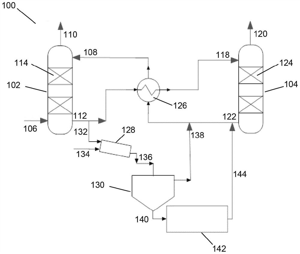
[0154] Already using 0.4 metric tons / day of CO located in lignite power stations 2 capture equipment for extended pilot plant testing, the CO 2 The capture device is configured with an absorption tower (102), a desorption tower (104) and a heat exchanger (126), generally as figure 1 depicted in . Capture equipment to take 80m directly from the power station 3 / h flow of flue gas slipstream operation.

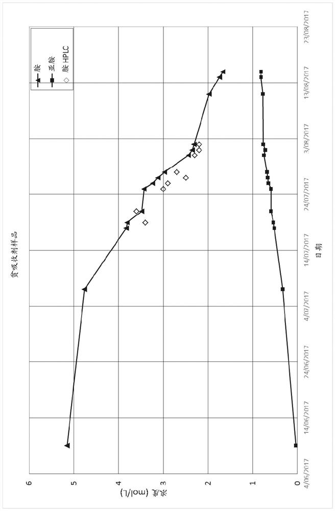
[0155]Exercise using 6 mol / L of aqueous 3-AMPy (61 wt% 3-AMPy and 39 wt% water) was operated for a duration of approximately 1500 hours (63 days). During operation, the performance of the plant was evaluated in terms of reboiler energy requirements and amine degradation was monitored. A single major degradation product formed was also identified and characterized. Achieved 2.9GJ / metric ton of CO without and with cold-rich split process configurations, respectively 2 and 2.6GJ / metric...

Embodiment 2

[0160] Example 2. Pilot plant test using an aqueous absorbent comprising 3 mol / L of 3-AMPy and 3 mol / L of AMP

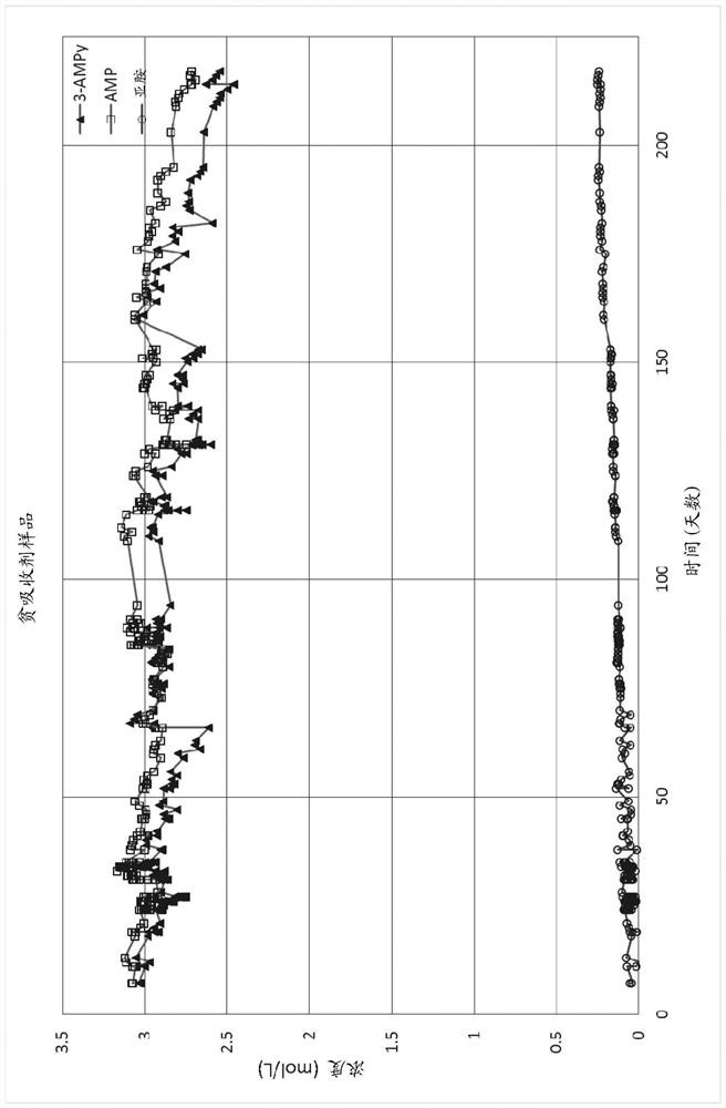
[0161] Based on the degradation mechanism of the above scheme, it is considered that if 3-AMPy is formulated with a stronger base to reduce the 2 formation of protonated 3-AMPy during absorption, its degradation can be inhibited. 2-Amino-2-methyl-1-propanol (AMP) was chosen as the amine for formulation due to its required basicity and known 2 Capture applications are robust. AMP does not interact with CO 2 reacts directly, but acts as a base to preferentially accept the protons released when 3-AMPy reacts. Simulations indicated that the concentrations used in aqueous absorbents of 3 mol / L 3-AMPy and 3 mol / L AMP were optimal for reducing degradation and maintaining capture performance.

Embodiment 3

[0164] Example 3. Comparison of the absorbents of Examples 1 and 2 with MEA

[0165] The pilot plant was also operated with 5 mol / L (30 wt%) aqueous monoethanolamine (MEA) for approximately 500 hours. This allows determining the optimal reboiler duty for each absorbent via parametric studies. These optimum reboiler duty and amine degradation rates are shown in the table below and are for the standard plant configuration (no rich split). It should be noted that the MEA degradation information was obtained from the literature, since the MEA was only run for short durations in the pilot plant.

[0166]

[0167] *Degradation rate obtained from the book P. Feron, Absorption-Based Post-Combustion Capture of Carbon Dioxide, Elsevier (2016).

[0168] Oxidative degradation of monoethanolamine is known to produce organic acids (such as formic and oxalic acids) and a wide variety of other products, many of which are highly soluble in aqueous absorbent solutions. The degradation pro...


PUM

PropertyMeasurementUnit
viscosityaaaaaaaaaa

Abstract

The invention provides a process for regenerating a liquid absorbent, comprising: contacting the liquid absorbent with a hydrophobic medium, wherein the liquid absorbent comprises at least one amine of Formula (I) and degradation product thereof comprising at least one imine of Formula (II), wherein each Ar is independently an aromatic group and each R is independently selected from hydrogen, an organyl group and NH2; and selectively extracting the degradation product into or through the hydrophobic medium.

Description

technical field [0001] The present invention relates to a process for regenerating liquid absorbents comprising amines and their imine degradation products. The process includes contacting a liquid absorbent with a hydrophobic medium and selectively extracting degradation products into or through the hydrophobic medium. The process is particularly suitable for CO capture from gas streams 2 It would be convenient to disclose the invention in the context of this exemplary application. [0002] Background of the invention [0003] carbon dioxide (CO 2 ) emissions are considered to be the main cause of the greenhouse effect and global warming. In the Kyoto Protocol, the United Nations Framework Convention on Climate Change has set targets for reducing greenhouse gas emissions. [0004] Atmospheric CO reduction 2 One method of emission is through atmospheric CO 2 capture and subsequent geological storage. In post combustion capture, the CO from the flue gas is first removed...

Claims


Application Information

Patent Timeline
Patent Type & Authority Applications(China)
IPC IPC(8): B01D53/14C07D213/38C07D213/53
CPCB01D53/1425B01D53/1475B01D53/1493B01D2252/204B01D2257/504B01D2252/504B01D2252/20421B01D2252/20478B01D2252/20426B01D2252/2053B01D3/143Y02C20/40B01D2252/20431B01D53/1462B01D53/62B01D53/78B01D53/96B01D2252/20457B01D2257/304
Inventor 格雷姆·普克斯蒂迈克尔·韦伯斯特-加德纳威廉·康威杨琦R·贝内特P·费隆
Owner COMMONWEALTH SCI & IND RES ORG
Features
  • R&D
  • Intellectual Property
  • Life Sciences
  • Materials
  • Tech Scout
  • Unparalleled Data Quality
  • Higher Quality Content
  • 60% Fewer Hallucinations
Learn More