Electrically heated catalytic combustor

A catalytic burner, electric heater technology, applied in the direction of combustion chamber, combustion equipment, combustion method, etc.

Active Publication Date: 2021-07-23
JOHNSON MATTHEY PLC +1
View PDF42 Cites 0 Cited by
  • Summary
  • Abstract
  • Description
  • Claims
  • Application Information

AI Technical Summary

Problems solved by technology

This reduces the electrical power requirements of the system, but creates additional complexity and bulk by requiring a tapered diffuser section between the two catalyst cores

Method used


Image

  • Electrically heated catalytic combustor
  • Electrically heated catalytic combustor
  • Electrically heated catalytic combustor

Examples


Embodiment approach 1

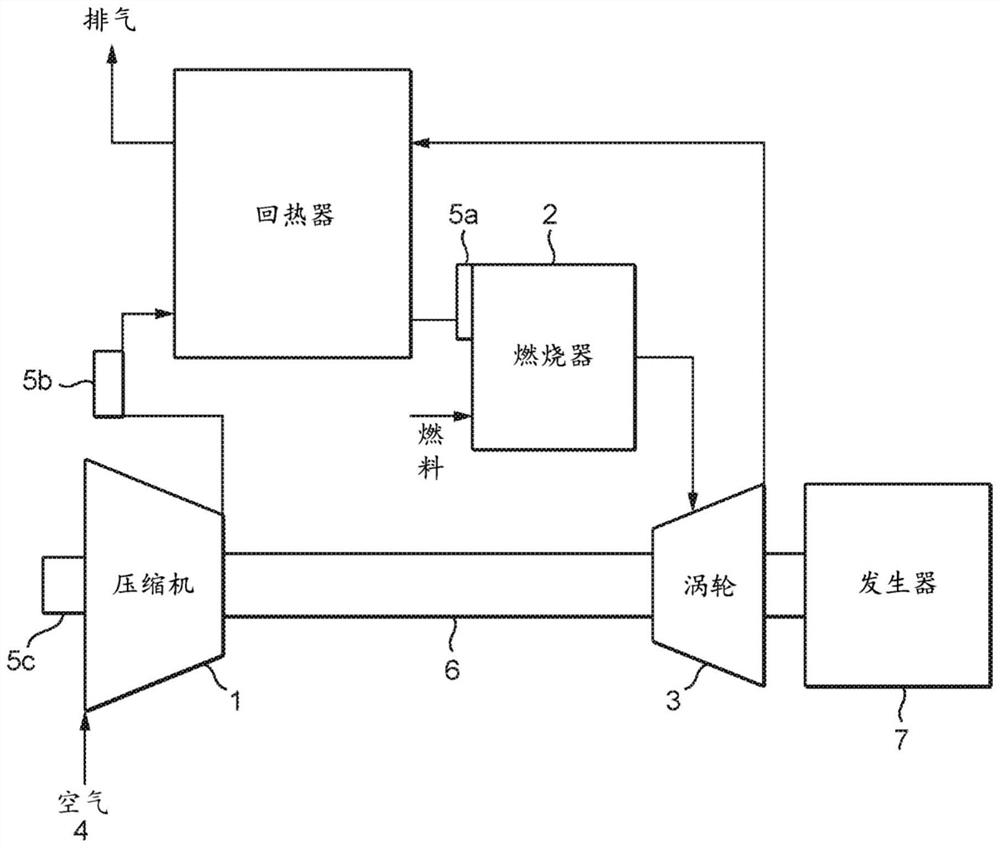
[0115] Implementation 1 A system comprising a regenerative gas turbine engine having a catalytic combustor comprising:

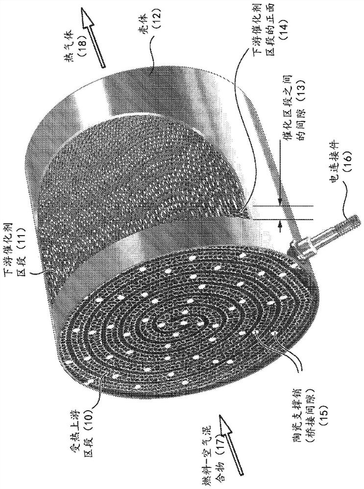
[0116] (a) an upstream section comprising an electric heater, and

[0117] (b) A downstream catalyst section, wherein the upstream section and the downstream catalyst section are disposed adjacent to each other and in fluid communication.

[0118] In certain aspects of this embodiment, a spacer is included between the upstream section and the downstream catalyst section; in other aspects, the two sections are in physical contact with each other; air gap. This air gap can be important to avoid short circuits in the metal substrate. For combined metal-ceramic substrates, it is possible to avoid discrete "interlayer gaps" across the diameter of the catalyst. In other aspects, there may also be a ceramic insulating connection between two segments constituting a physical support with electrical insulation.

Embodiment approach 2

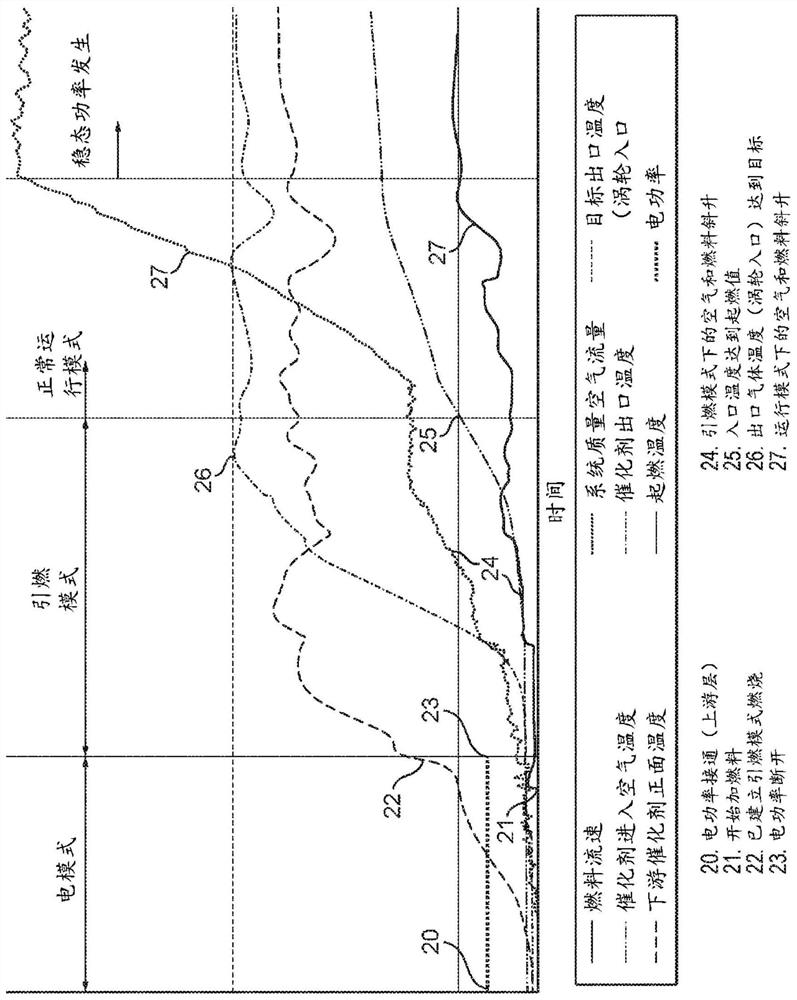
[0119] Embodiment 2 The system of embodiment 1, wherein the upstream section including the electric heater is the only source of ignition in the catalytic combustor. In independent aspects of this embodiment, some embodiments have and do not have a separate ignition source, but preferably there are no ignition sources other than electric heaters. In other respects, the system does not contain additional igniters anywhere in the system.

Embodiment approach 3

[0120] Embodiment 3 The system according to embodiment 1 or 2, wherein the upstream section and the downstream catalyst section are integrated in a single unit. In certain independent aspects of this embodiment, the two sections are compositionally identical or different from each other due to the substrate material or catalyst material contained within each section.


PUM


Abstract

The present disclosure is directed to a system comprising a recuperated gas turbine engine with a catalytic combustor, and methods of operating the same, the catalytic combustor comprising: (a) an upstream section comprising an electrical heater and (b) a downstream catalyst section, wherein the upstream section and the downstream catalyst section are disposed adjacent to and in fluid communication with one another.

Description

technical field [0001] The present disclosure relates to apparatus and methods for igniting and controlling an air / fuel mixture in catalytic combustors, particularly those of regenerative gas turbine engines, where such engines may be used in power generation and propulsion applications. Background technique [0002] Gas turbines are used in both stationary and mobile applications for power generation and vehicle propulsion on land, sea and air. The need to reduce harmful exhaust emissions from heat engines of all types is recognized, and an essential part of many solutions is a more efficient and cleaner combustion system. In the field of gas turbine engines, combustion technologies for liquid fuels and gaseous fuels have emerged, such as dry low NOx (DLN) combustion, rich-quenched-lean (RQL) combustion, and catalytic combustion. Catalytic solutions remain unsurpassed for NOx reduction, but typically require some form of pre-combustor to maintain the catalyst above light-o...

Claims


Application Information

Patent Timeline
IPC IPC(8): F23R3/40F23R3/00
CPCF23R3/40F23R3/005F02C7/224F02C7/264F05D2260/213F05D2260/99F23R3/30
Inventor N·卡彭特G·钱德勒J·吉登尼S·赫林C·摩根T·奥康奈尔M·威尔克斯
Owner JOHNSON MATTHEY PLC
Why Eureka
Try Eureka