Eureka AIR delivers breakthrough ideas for toughest innovation challenges, trusted by R&D personnel around the world.

Medical image recording control system

A control system and medical image technology, applied in medical images, image communication, medical equipment, etc., can solve the problems of complicated images

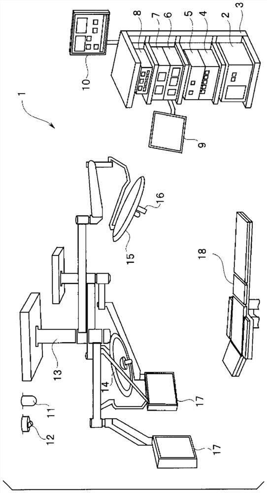
Pending Publication Date: 2021-07-23
OLYMPUS CORP
View PDF1 Cites 0 Cited by
  • Summary
  • Abstract
  • Description
  • Claims
  • Application Information

AI Technical Summary

Problems solved by technology

Therefore, it is possible to record images from all image sources at the same time. However, when checking images after surgery, it becomes complicated to merge the time axes of multiple images and reproduce the recorded images in accordance with the progress of the operation.
In addition, there is also the problem that recording images of all image sources requires a storage device with a large storage capacity

Method used


Image

  • Medical image recording control system
  • Medical image recording control system
  • Medical image recording control system

Examples


Deformed example 1

[0122] Figure 6 It is a block diagram showing a configuration related to image recording in a medical system 1A according to Modification 1. FIG.

[0123] exist Figure 6 in, right with figure 2 The same constituent elements are given the same symbols and descriptions thereof are omitted.

[0124] Medical system 1A includes 2 laparoscopes and 2 treatment devices. Specifically, the medical system 1A includes a first laparoscope camera device 8 and a second laparoscope camera device 41 , a first laparoscope light source device 6 and a second laparoscope light source device 42 , a first pneumoperitoneum The device 7 and the second pneumoperitoneum device 43 , and the first treatment device 4 and the second treatment device 44 .

[0125] The image sources are four of the first laparoscope camera device 8 , the second laparoscope camera device 41 , the indoor camera 12 , and the surgical camera 16 .

[0126] Down converter 19A has the same function as down converter 19, but ...

Deformed example 2

[0149] Figure 9 It is a block diagram showing the configuration related to image recording in the medical system 1B according to Modification 2.

[0150] exist Figure 9 in, right with figure 2 and Figure 5 The same constituent elements are given the same symbols and descriptions thereof are omitted.

[0151] Medical system 1B includes 1 laparoscope, 1 endoscope and 2 treatment equipments. Specifically, the medical system 1B includes a laparoscope camera device 8 and an endoscope camera device 51, a laparoscope light source device 6 and an endoscope light source device 52, an insufflation device 7, and a first treatment device 4 and the second treatment equipment 53. The first treatment device 4 is used under observation by the laparoscope camera device 8 , and the second treatment device 53 is used under observation by the endoscope light source device 52 .

[0152] The image sources are four of the laparoscope camera device 8 , the endoscope camera device 51 , the r...


PUM


Abstract

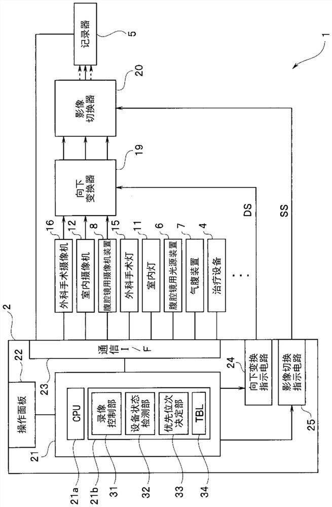
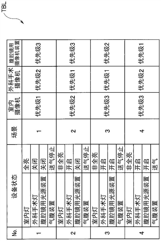
A medical image recording control system (1) comprises: an apparatus state detection unit (32) for detecting states of a plurality of apparatuses; a priority order determination unit (33) which, from the results of detection by the apparatus state detection unit and on the basis of the states of two or more apparatuses including at least one of a room light, a surgical light, and a light source device for endoscope included in the plurality of apparatuses, determines a priority order of at least one video source apparatus among a plurality of video source apparatuses included in the plurality of apparatuses; a video switcher (20) for selectively switching and outputting a plurality of video signals of the plurality of video source apparatuses; a recorder (5) for recording at least one video signal output from the video switcher (20); and a video source switching instruction output circuit (25) for outputting a switching instruction signal (SS) corresponding to the priority order of the at least one video source apparatus determined by the priority order determination unit (33) to the video switcher (20).

Description

technical field [0001] The invention relates to a medical image recording control system for recording medical images. Background technique [0002] At the time of surgery, patient data and images are recorded. The recorded data and images are used to confirm the steps, procedures, etc. of the performed surgery after the surgery. For example, Japanese Patent Application Laid-Open No. 2005-135344 proposes a technique of recording various sensor data during surgery and recording images of various cameras. [0003] In addition, since there are various image sources such as room cameras, surgical cameras, and laparoscopes in the operating room, the image sources to be recorded by the video recording device are switched according to the progress of the operation so that the images after the operation Confirmation made easy. [0004] Switching, that is, selection of video sources to be recorded is performed by a nurse or the like, so switching errors, forgetting to record, and ...

Claims


Application Information

Patent Timeline
IPC IPC(8): H04N5/77G16H40/20H04N5/225H04N5/92H04N7/18
CPCG16H40/20H04N7/18H04N5/77H04N9/80A61B1/04A61B1/06A61B1/3132A61B1/00006A61B1/045G16H30/20A61B1/0655G16H40/60
Inventor 奥泽康裕
Owner OLYMPUS CORP
Why Eureka
Eureka Blog
Learn More