Automatic paint spraying production line with movable processing chamber

A technology of activity treatment and treatment room, which is applied in the direction of spraying booths and spraying devices, which can solve the problems of large workload, poor painting effect, waste of paint mist, etc., and achieve the effect of flexible adjustment, reducing the amount of spraying paint, and ensuring the effect of spraying paint

Active Publication Date: 2021-07-27
泉州芸台科技有限公司
View PDF9 Cites 3 Cited by
  • Summary
  • Abstract
  • Description
  • Claims
  • Application Information

AI Technical Summary

Problems solved by technology

However, when painting smaller workpieces, in the case of a large internal space, the painting components on both sides are far away, the painting effect is poor and a large amount of paint mist will be wasted
And because the circulating track passes through the inside of the processing chamber, and the processing chamber is directly erected on the ground, if you want to temporarily replace the processing chamber with a processing chamber with a smaller internal space, you not only need to disassemble the processing chamber body, but also It is necessary to process the circuit connected to the processing room, and possibly the circulating track, and then to assemble, erect and connect the new processing room, which requires a large workload and is troublesome

Method used


Image

  • Automatic paint spraying production line with movable processing chamber
  • Automatic paint spraying production line with movable processing chamber
  • Automatic paint spraying production line with movable processing chamber

Examples


Embodiment 1

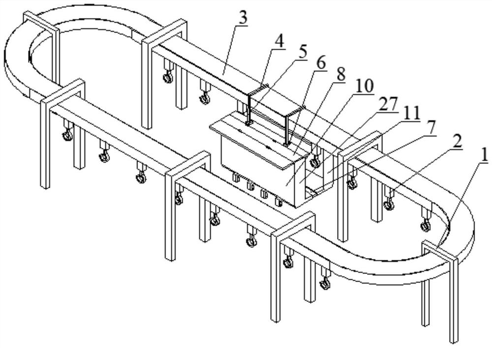
[0055] Please refer to Figure 1 to Figure 3 , Embodiment 1 of the present invention is:

[0056] An automatic painting production line with a movable processing chamber, including a support frame 1, a processing chamber, a fixed structure, a hook 2 connected under the circular track 3, a circular track 3 connected to the support frame 1, and two groups of moving painting parts up and down twenty two.

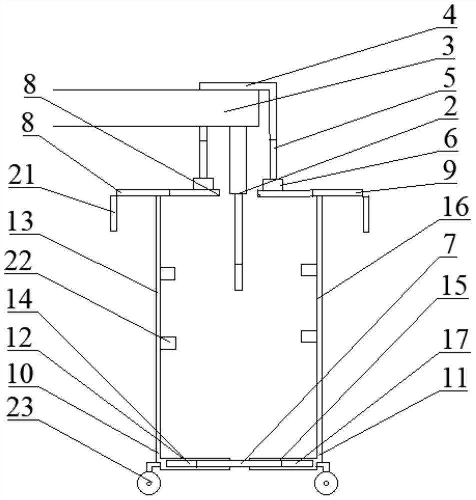
[0057] Such as figure 1 and figure 2 As shown, the fixed structure includes two fixed frames 4 erected above the circulating track 3, telescopic rods 5 connected below both ends of the fixed frame 4, and a fixed cover 6 arranged at the other end of the telescopic rod 5 connected to the fixed frame 4 The processing chamber is located below the circulation track 3, and the treatment chamber includes a central bottom plate 7, a left top plate 8 and a right top plate 9 bounded by the circulation track 3, and a left bottom assembly 10 and a right bottom assembly 11 whose cross s...

Embodiment 2

[0068] Please refer to Figure 4 to Figure 6 , the second embodiment of the present invention is:

[0069] An automatic painting production line with a movable processing chamber, including a support frame 1, a processing chamber, a fixed structure, a hook 2 connected under the circular track 3, a circular track 3 connected to the support frame 1, and two groups of moving painting parts up and down twenty two;

[0070] Such as Figure 5 and Figure 6 As shown, the difference from Embodiment 1 is that the cooperation of the left transverse part 12, the right transverse part 15 and the center bottom plate 7 is:

[0071]The end of the left horizontal part 12 far away from the left vertical part 13 is provided with a left receiving groove 14, and the end of the right horizontal part 15 far away from the right vertical part 16 is provided with a right receiving groove 17, and the central bottom plate 7 is close to both sides of the entrance and exit of the processing chamber. A...


PUM


Abstract

The invention discloses an automatic paint spraying production line with a movable processing chamber. The automatic paint spraying production line comprises a supporting frame, the processing chamber, a fixing structure, lifting hooks connected to the lower portion of a circulating track, the circulating track connected with the supporting frame and two sets of paint spraying pieces moving up and down, wherein the processing chamber is located below the circulating track and comprises a center bottom plate, a left top plate, a right top plate, a left bottom assembly and a right bottom assembly, the left top plate and the right top plate are bounded by the circulating track, the sections of the left bottom assembly and the right bottom assembly are L-shaped, and a left transverse part of the left bottom assembly and a right transverse part of the right bottom assembly are slidably connected with the two ends of the center bottom plate; and the end, away from the left transverse part, of a left vertical part of the left bottom assembly is slidably connected to the bottom of the left top plate, and the end, away from the right transverse part, of a right vertical part of the right bottom assembly is slidably connected to the bottom of the right top plate. According to the automatic paint spraying production line, the size of the processing chamber can be controlled, so that flexible adjustment of the size of the processing chamber is achieved, the paint spraying effect is guaranteed, and the paint spraying amount is reduced.

Description

technical field [0001] The invention relates to the technical field of industrial manufacturing, in particular to an automatic painting production line with a movable processing chamber. Background technique [0002] In industrialized production, the application of automated production lines has been widely popularized. The existing automatic painting production line generally erects the processing chamber on the ground, and the circulation track passes through the interior of the processing chamber. In order to be able to paint larger workpieces, the volume and internal space of the processing chamber are generally larger, and the painting assembly needs to be moved up and down to ensure the painting effect. And when painting a smaller workpiece, in the case of a large internal space, the painting components on both sides are far away, the painting effect is poor and a large amount of paint mist will be wasted. And because the circulating track passes through the inside o...

Claims


Application Information

Patent Timeline
Patent Type & Authority Applications(China)
IPC IPC(8): B05B16/00B05B16/40B05B13/02
CPCB05B16/90B05B13/0264B05B16/40Y02P70/10
Inventor 钟松杏张阳川林宇鹏吴泽琛
Owner 泉州芸台科技有限公司
Why Eureka
Try Eureka