Check patentability & draft patents in minutes with Patsnap Eureka AI!

Clamping device for mechanical lathe machining

A lathe processing and mechanical technology, applied in conveyors, conveyor objects, transportation and packaging, etc., can solve problems such as damage to component accuracy, affect component quality, and affect production efficiency, and achieve easy operation, high work efficiency, and labor saving. cost effect

Pending Publication Date: 2021-07-27
SUZHOU UNIV OF SCI & TECH
View PDF0 Cites 2 Cited by
  • Summary
  • Abstract
  • Description
  • Claims
  • Application Information

AI Technical Summary

Problems solved by technology

[0002] At present, in the processing of mechanical lathes, most of the processing components need to be manually transported and picked up, and a few parts with large mass and volume need to be hoisted. This method first has potential safety hazards. When manually handling components, it is easy to bump and damage the precision of the components, thereby affecting the quality of the components.
Secondly, the workers increase a lot of physical labor, the handling efficiency is low, and the overall production efficiency is affected.

Method used


Image

  • Clamping device for mechanical lathe machining
  • Clamping device for mechanical lathe machining
  • Clamping device for mechanical lathe machining

Examples


Embodiment Construction

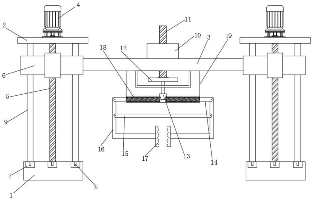
[0034] Such as Figure 1 to Figure 3 As shown, the present invention includes a base 1, a lifting frame, a crossbeam 3 and a clamping assembly. Two bases 1 are fixed and installed in parallel on the workshop floor and located on both sides of the lathe. The lifting frame is slidably connected to the base 1. A crossbeam 3 is arranged between the lifting frames, and the clamping assembly is installed on the crossbeam 3;

[0035] The bottom of the lifting frame is slidingly connected with the base, the top of the lifting frame is provided with a top plate 2, and the first screw motor 4 is fixedly installed on the top plate 2, and the lifting frame includes a first leading screw 5 and two Support columns 9, two support columns 9 are evenly distributed on the peripheral side of the first lead screw 5, and the first lead screw 5 is equipped with a lift platform 6 that moves up and down with the rotation of the first lead screw 5, and the lift platform 6 Simultaneously slide and soc...


PUM


Abstract

The invention provides a clamping device for mechanical lathe machining. The clamping device comprises bases, lifting frames, a cross beam and a clamping assembly, the two bases are symmetrically arranged, the lifting frames are vertically connected to the bases in a sliding mode, the cross beam is arranged between the two lifting frames, and the clamping assembly is installed on the cross beam. The lifting frames are lead screw lifting devices, lifting tables capable of floating up and down are arranged on the lifting frames, the cross beam is fixedly arranged between the lifting tables, and the clamping assembly is a self-locking clamping device formed in the mode that a lead screw stretches out and draws back to transmit power to abut against the lifting tables. The clamping device is scientific and reasonable in structural design, stable in transmission and stable in clamping, self-locking torque is indirectly conducted, components machined by a lathe are effectively protected, and clamping and transferring of the components are facilitated.

Description

technical field [0001] The invention relates to a clamping device, in particular to a clamping device for mechanical lathe processing. Background technique [0002] At present, when processing mechanical lathes, most of the processing components need to be handled manually, and a few parts with large mass and volume need to be hoisted. This method first has potential safety hazards. When manually handling components, it is easy to bump and damage the precision of the components, thereby affecting the quality of the components. Secondly, the workers have increased a lot of physical labor, and the handling efficiency is low, which affects the overall production efficiency. [0003] In recent years, with the shortage of labor resources and the improvement of product quality requirements, there is an increasing need for a mechanized clamping device to clamp and move metal components. Contents of the invention [0004] The technical problem to be solved by the present inventio...

Claims


Application Information

Patent Timeline
IPC IPC(8): B65G47/90
CPCB65G47/901B65G47/905B65G2201/02
Inventor 曹自洋马振武殷振卢金斌苗情戴晨伟潘杰倪家伟许威朱译文
Owner SUZHOU UNIV OF SCI & TECH
Features
  • R&D
  • Intellectual Property
  • Life Sciences
  • Materials
  • Tech Scout
  • Unparalleled Data Quality
  • Higher Quality Content
  • 60% Fewer Hallucinations
Learn More