Constant-temperature and constant-humidity test box
A constant temperature and humidity test and test chamber technology, which is applied in the field of test chambers, can solve problems such as high internal temperature, complicated water addition process to the water collection tank, and worker injuries
- Summary
- Abstract
- Description
- Claims
- Application Information
AI Technical Summary
Problems solved by technology
Method used
Image

Examples
Embodiment 1
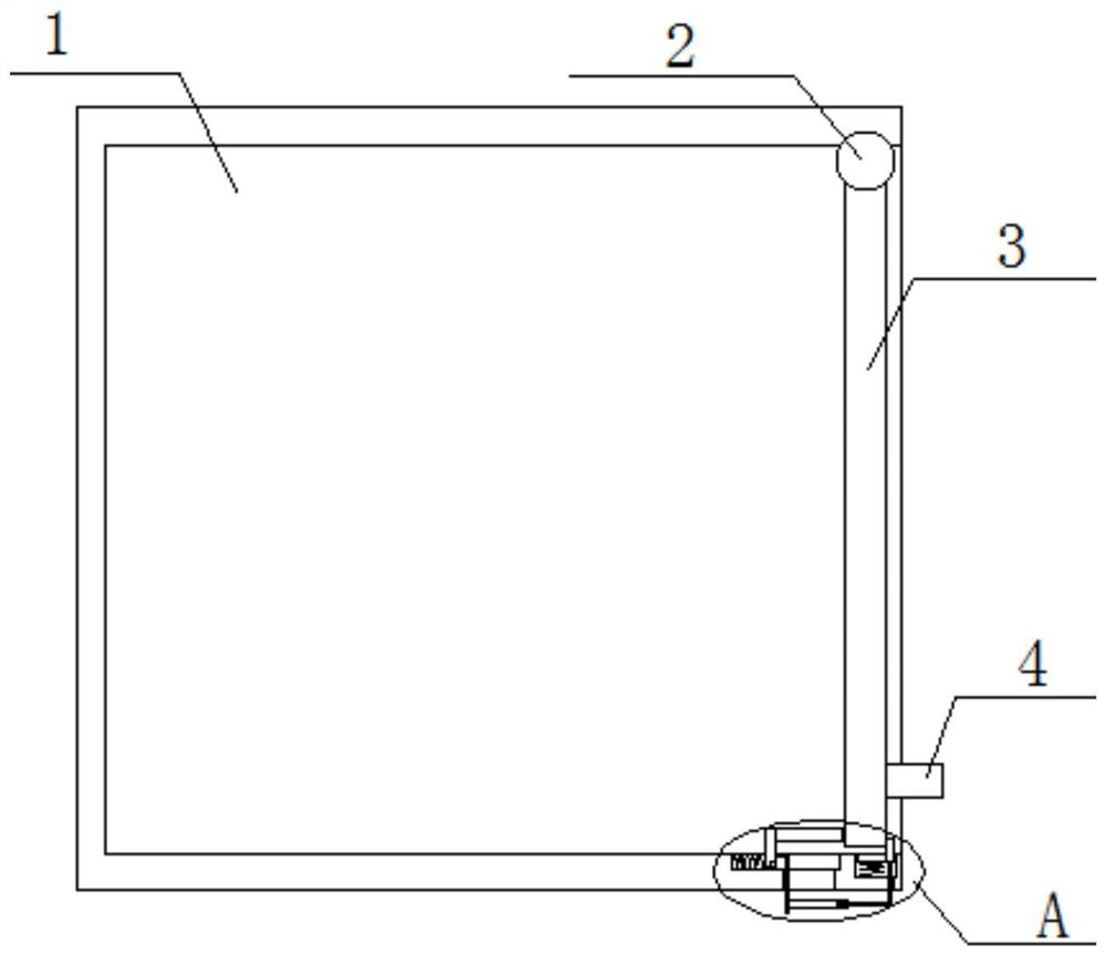
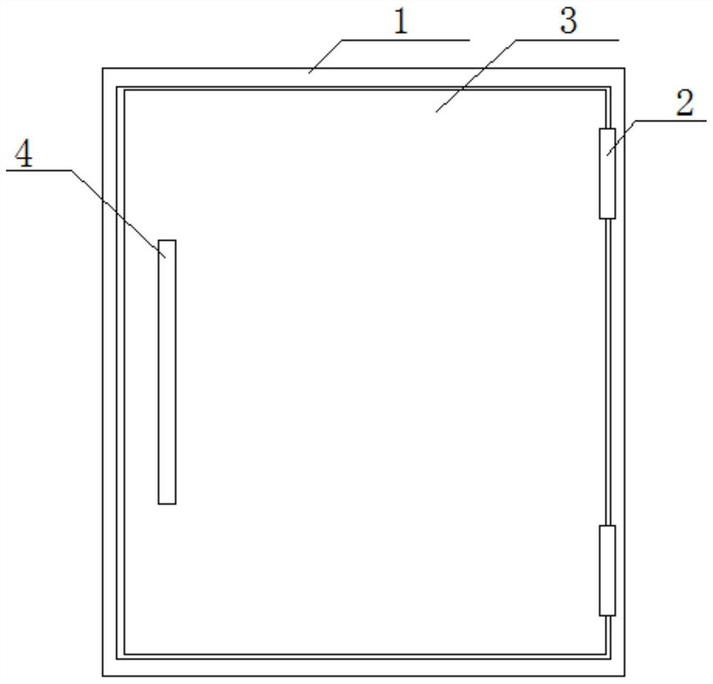
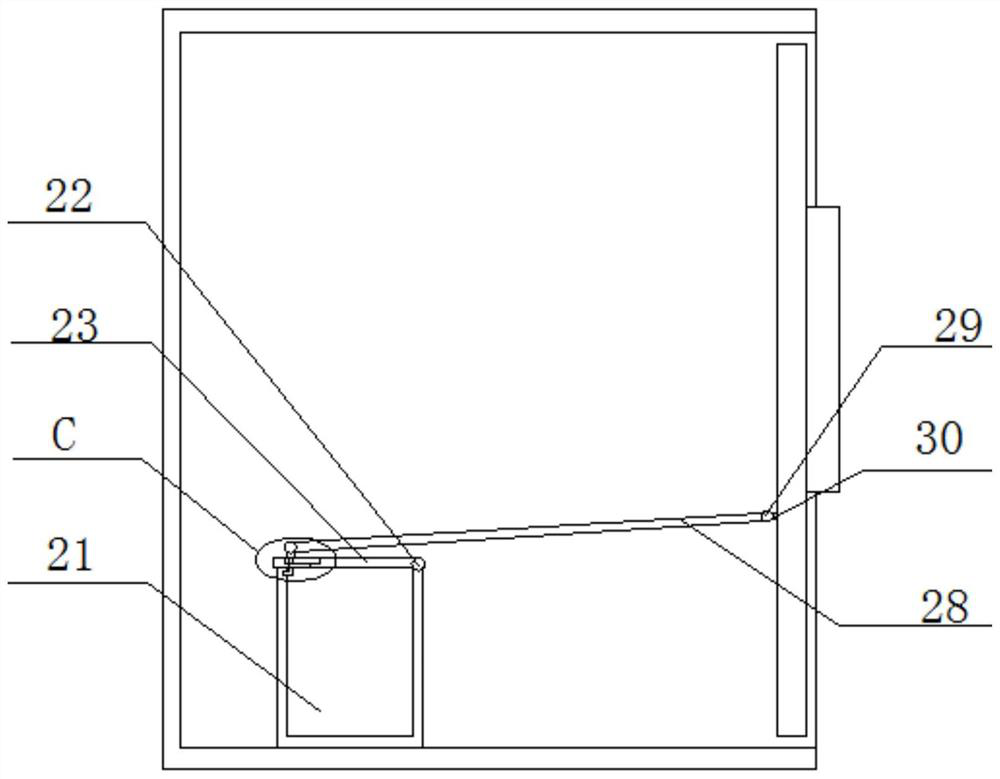
[0027] refer to Figure 1-6 , a constant temperature and humidity test chamber, comprising a test chamber 1, one side of the test chamber 1 is an open structure, and the top and bottom inner walls of the test chamber 1 near the opening are equipped with a first rotating shaft 2 for rotation, the first rotating shaft A baffle 3 is fixedly installed on the 2, and the baffle 3 is compatible with the test box 1. A handle 4 is fixedly installed on the side of the baffle 3 far away from the test box 1, and a handle 4 is fixedly installed on the side of the bottom of the test box 1 close to the opening. There is a groove 5, and a sliding plate 6 is slidably installed in the groove 5, and one end of the first spring 7 is fixedly installed on the bottom of the sliding plate 6, and the other end of the first spring 7 is fixedly connected with the bottom inner wall of the groove 5, and the sliding plate One end of 6 is fixedly installed with one end of gear rod 8, and the other end of ge...
Embodiment 2
[0029] In the present invention, one end of the first sliding rod 10 extending to the outside of the test chamber 1 is fixed with one end of the telescopic rod 11, and the other end of the telescopic rod 11 is slidably installed with a sleeve rod 12, and the sleeve rod 12 is compatible with the telescopic rod 11. , the telescopic rod 11 is used for the above.
[0030] In the present invention, the bottom of the test box 1 is provided with a first sliding groove 13 on the inner wall of one side near the opening, and a first sliding block 14 is slidably installed in the first sliding groove 13, and one side of the first sliding block 14 is fixedly installed. There is an end of the push rod 15, the other end of the push rod 15 is in contact with one side of the baffle plate 3, one end of the second spring 16 is fixedly installed on one side of the first slide block 14, and the other end of the second spring 16 is connected to the first end of the second spring 16. One side of a s...
Embodiment 3
[0037] A constant temperature and humidity test chamber, comprising a test chamber 1, one side of the test chamber 1 is an open structure, and the top and bottom inner walls of the test chamber 1 near the opening are rotatably installed with a first rotating shaft 2, the first rotating shaft 2 A baffle 3 is fixedly welded on the top, and the baffle 3 is compatible with the test box 1. The side of the baffle 3 away from the test box 1 is fixedly welded with a handle 4, and the bottom of the test box 1 is chiseled on the inner wall of the side near the opening. Groove 5, a sliding plate 6 is slidably installed in the groove 5, and one end of the first spring 7 is fixedly welded on the bottom of the sliding plate 6, and the other end of the first spring 7 is fixedly connected with the bottom inner wall of the groove 5, and the sliding plate 6 One end of one end is fixedly welded with one end of the gear rod 8, and the other end of the gear rod 8 is in contact with one side of the ...
PUM
 Abstract
Description
Claims
Application Information
 - R&D
- Intellectual Property
- Life Sciences
- Materials
- Tech Scout
- Unparalleled Data Quality
- Higher Quality Content
- 60% Fewer Hallucinations
Browse by: Latest US Patents, China's latest patents, Technical Efficacy Thesaurus, Application Domain, Technology Topic, Popular Technical Reports.
© 2025 PatSnap. All rights reserved.Legal|Privacy policy|Modern Slavery Act Transparency Statement|Sitemap|About US| Contact US: help@patsnap.com