Precise cutting equipment for medical sponge
A kind of cutting equipment and precise technology, applied in metal processing and other directions, can solve problems such as uneven sponge, achieve the effect of increasing accuracy, avoiding movement, and cutting accurately
- Summary
- Abstract
- Description
- Claims
- Application Information
AI Technical Summary
Problems solved by technology
Method used
Image

Examples
Embodiment 1
[0066] A medical sponge precision cutting equipment, such as figure 1 As shown, including the bottom plate 1, the strut 2, the table 3, the first guide rail 4, the support assembly 5, the cutting assembly 6 and the stable assembly 7, and the bottom plate 1 is provided with a strut 2, between the top of the strut 2. The workbench 3 is connected. The first rail 4 is provided on the top of the top of the table 3. The first rail 4 is connected between the support assembly 5, and the support assembly 5 is provided with a cutting assembly 6, and the support assembly 5 is stable on the support assembly 5. Component 7.
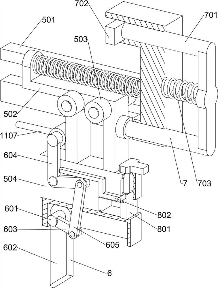
[0067] like image 3 and Figure 4As shown, the support assembly 5 includes a second rail 501, a shaped slider 502, a roller 503, and a mounting block 504, and a second rail 501 is slidably connected between the first rail 4, and the second rail 501 is slidable. The slider 502 is connected between the shaped slider 502 and the second rail 501, and the outer side surface of ...
Embodiment 2
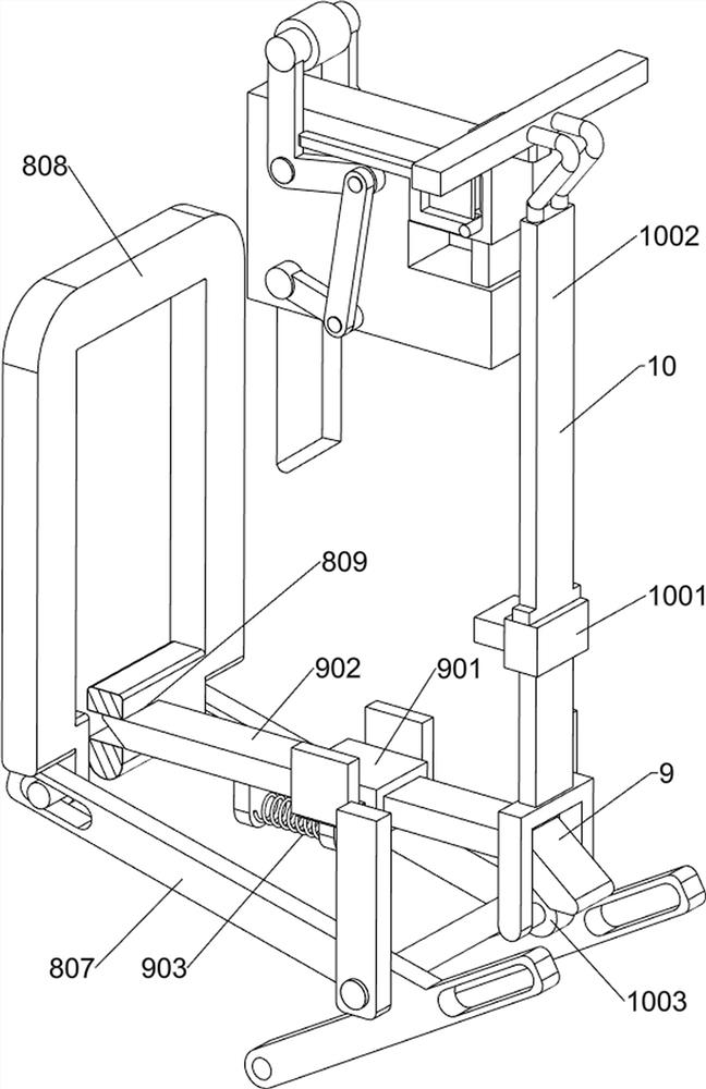
[0072] On the basis of Example 1, such as Figure 4 , Figure 7 and Figure 8 As shown, it is also included, and the finite binding assembly 8 includes a square slider 801, a shaped rod 802, a support rod 803, a movable block 804, a second spring 805, a first contact frame 806, a shaped turn rod 807, a limit The bit block 808, the card slot 809, the L-type turn rod 810 and the connecting rod 811, the right sliding type of the mounting block 504 is provided with a square slider 801, and the front side of the square slider 801 is provided with shaped rod 802, and the table 3 is provided. There is a support rod 803, and a plurality of movable blocks 804 are slidable on the support rod 803, and two second spring 805 are connected between the movable block 804 and the support rod 803, and the top portion of the movable block 804 is provided with a first contact frame 806. The table 3 is sliding in the left and right sides of the table, and there is a plurality of limit blocks 808, and the...
Embodiment 3
[0077] On the basis of Example 2, such as figure 2 and Image 6 As shown, there is a moving assembly 11, and the moving assembly 11 includes a servo motor 1101, a second rotating shaft 1102, a first transmission wheel 1103, a second drive wheel 1104, a belt 1105, a winding wheel 1106, and a drawn rope 1107, second The servo motor 1101 is provided on the left side of the guide rail 501, and the servo motor 1101 output shaft is connected to the first drive wheel 1103, and the second guide rail 501 is provided with the second rotating shaft 1102, and the second rotating wheel is provided on the front side of the second shaft 1102. 1104. The first shift wheel 1103 is connected between the belt 1105 between the second drive wheels 1104, and the second rotating shaft 1102 is provided with a wire wheel 1106, and the wire wheel 1106 is wound around the pulley 1107, and the drawing rope 1107 is another end. Connected to the tie rod 604.
[0078] When the sponge is fooled and the position of...
PUM
 Abstract
Description
Claims
Application Information
 - R&D
- Intellectual Property
- Life Sciences
- Materials
- Tech Scout
- Unparalleled Data Quality
- Higher Quality Content
- 60% Fewer Hallucinations
Browse by: Latest US Patents, China's latest patents, Technical Efficacy Thesaurus, Application Domain, Technology Topic, Popular Technical Reports.
© 2025 PatSnap. All rights reserved.Legal|Privacy policy|Modern Slavery Act Transparency Statement|Sitemap|About US| Contact US: help@patsnap.com