Coaxial homodromous propeller with variable phase difference

A technology of propeller and phase difference, which is applied in the direction of propeller, transportation and packaging, aircraft parts, etc., can solve the problems of propeller aerodynamic efficiency reduction, unfavorable dynamics, shortening the range of propeller aircraft, etc.

Active Publication Date: 2021-07-30
BEIHANG UNIV
View PDF6 Cites 0 Cited by
  • Summary
  • Abstract
  • Description
  • Claims
  • Application Information

AI Technical Summary

Problems solved by technology

[0004] For the single-propeller scheme, although increasing the solidity of the rotor can increase the thrust of the single-propeller propulsion device, this method also increases the unfavorable aerodynamic interference between the blades of the propeller, so that the aerodynamic efficiency of the propeller increases with the increase of thrust. increasing and decreasing
For the coaxial reverse propeller scheme, this scheme can ensure that the two propellers are in a better rotor solidity, but because the rotation directions of the two propellers are opposite, the rear propeller will pass through the wake of the front propeller continuously. It will produce a complex and periodic dynamic adverse aerodynamic disturbance, which will reduce the overall aerodynamic efficiency of the coaxial reverse propeller propulsion device
The aerodynamic efficiency of the propeller determines the thrust-to-power ratio of the aircraft. The decrease in aerodynamic efficiency means that the engine power required by the propeller increases under the same thrust, and the fuel consumption rate increases, which will shorten the range of the propeller aircraft.
There is also a constant high level of aerodynamic noise due to the periodic nature of the adverse aerodynamic disturbances of the counter-rotating coaxial propellers
This noise will reduce the comfort of the people on board and make the aircraft less concealed

Method used


Image

  • Coaxial homodromous propeller with variable phase difference
  • Coaxial homodromous propeller with variable phase difference
  • Coaxial homodromous propeller with variable phase difference

Examples


Embodiment Construction

[0034] In order to understand the above-mentioned purpose, features and advantages of the present invention more clearly, the present invention will be further described in detail below in conjunction with the accompanying drawings and specific embodiments. It should be noted that, in the case of no conflict, the embodiments of the present invention and the features in the embodiments can be combined with each other.

[0035] In the following description, many specific details are set forth in order to fully understand the present invention. However, the present invention can also be implemented in other ways different from those described here. Therefore, the protection scope of the present invention is not limited by the specific details disclosed below. EXAMPLE LIMITATIONS.

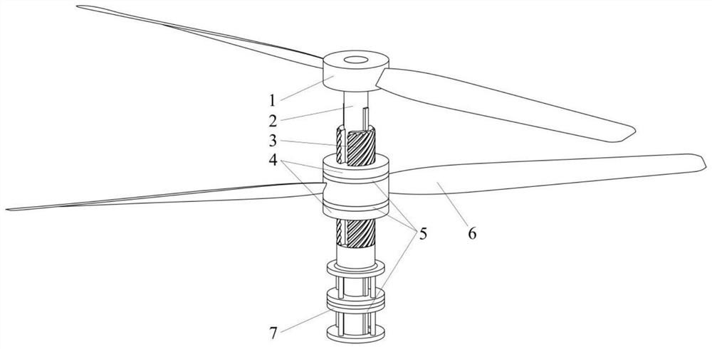
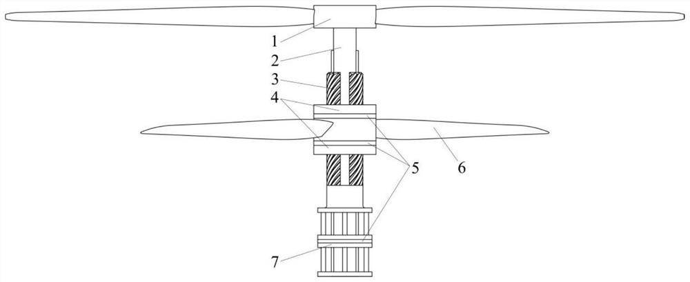
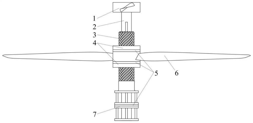
[0036] The present invention proposes a propeller that uses coaxial rotation in the same direction, that is, two propellers with coincident rotating axes are arranged front and rear along the thrust di...


PUM


Abstract

The invention discloses a coaxial homodromous propeller with variable phase difference. Two propellers with coincident rotating shafts are arranged front and back in the thrust direction of the propellers and comprise front propellers, propeller rotating shafts, sliding sleeves and rear propellers. The two propellers rotate in the same direction. A certain phase difference exists between the rear propeller and the front propeller to ensure that the rear propeller is far away from the wake flow spiral surface of the front propeller. In the actual operation process, if the wake flow helicoid approaches the rear propeller due to the change of the forward ratio, the rear propeller adjusts the phase difference formed between the rear propeller and the front propeller through the forward and backward movement of the sleeve, so that the rear propeller can still be located outside the wake flow area of the front propeller. According to the invention, adverse aerodynamic interference and aerodynamic noise of a coaxial propeller system are reduced.

Description

technical field [0001] The invention belongs to the technical field of aircraft propulsion device design, in particular to a coaxial and same-direction propeller with variable phase difference. Background technique [0002] When the maximum diameter of the propeller is limited, the most important means to increase the thrust of the propeller is to increase the area of ​​the rotor blade, that is, to increase the solidity of the rotor. Increasing the solidity of the rotor can be achieved by increasing the chord length of the blade and increasing the number of blades. For example, propeller fighter jets in the 1930s mainly used two-bladed and three-bladed propellers, typical examples such as Yi-16 (two-bladed), La-9 (three-bladed), etc. But in the late 1940s, four-bladed propellers gradually became mainstream, such as Ki-84, P-51, etc. [0003] Considering that the efficiency of the propeller will decrease when the solidity of the rotor exceeds a certain range, the industry h...

Claims


Application Information

Patent Timeline
Patent Type & Authority Applications(China)
IPC IPC(8): B64C11/48
CPCB64C11/48
Inventor 蒋崇文李志豪胡姝瑶许晨豪高振勋李椿萱
Owner BEIHANG UNIV
Why Eureka
Try Eureka