A kind of unmanned aerial vehicle arresting hook, control method and unmanned aerial vehicle

An arresting hook and unmanned aerial vehicle technology, applied in the field of unmanned aerial vehicles, can solve the problems such as the inability to reset the automatic decoupling device of the unmanned aerial vehicle, the shortening of the landing and sliding distance of the arresting cable, and the occurrence of few products, so as to improve the success rate of go-around. , Improve the success rate of hanging rope, and inhibit the effect of bouncing

Active Publication Date: 2022-04-22
NANJING UNIV OF AERONAUTICS & ASTRONAUTICS +1
View PDF7 Cites 0 Cited by
  • Summary
  • Abstract
  • Description
  • Claims
  • Application Information

AI Technical Summary

Problems solved by technology

[0002] With the continuous advancement of drone technology, the application fields and prospects of drones are constantly expanding. With the increase of drone application scenarios, the types of drones, whether military or civilian, are increasing. Fixed-wing, multi-rotor small and medium-sized, medium-sized, and some medium- and large-scale UAVs need ejection devices to shorten the take-off distance and also need arresting cables to shorten the landing run distance. The problem of resetting the UAV automatic decoupling device as soon as possible to prepare for the next landing has become increasingly prominent. At the moment when UAV cluster work is becoming more and more important, the recovery efficiency is an important factor affecting the work efficiency of the fleet. Hook bouncing problem, leading to the failure of the hanging rope is not uncommon. The failure of the hanging rope will require the drone to go around immediately, but it will take time to judge whether the hanging rope is successful, resulting in insufficient go-around distance, and finally the drone crashes.
[0003] At present, for the above but not limited to the above occasions, there are few related products

Method used


Image

  • A kind of unmanned aerial vehicle arresting hook, control method and unmanned aerial vehicle
  • A kind of unmanned aerial vehicle arresting hook, control method and unmanned aerial vehicle
  • A kind of unmanned aerial vehicle arresting hook, control method and unmanned aerial vehicle

Examples


Embodiment Construction

[0036] In order to make the above objects, features and advantages of the present invention more comprehensible, specific implementations of the present invention will be described in detail below in conjunction with the accompanying drawings. In the following description, numerous specific details are set forth in order to provide a thorough understanding of the present invention. However, the present invention can be implemented in many other ways different from those described here, and those skilled in the art can make similar improvements without departing from the connotation of the present invention, so the present invention is not limited by the specific embodiments disclosed below.

[0037] It should be noted that when an element is referred to as being “fixed” to another element, it can be directly on the other element or there can also be an intervening element. When an element is referred to as being "connected to" another element, it can be directly connected to t...


PUM


Abstract

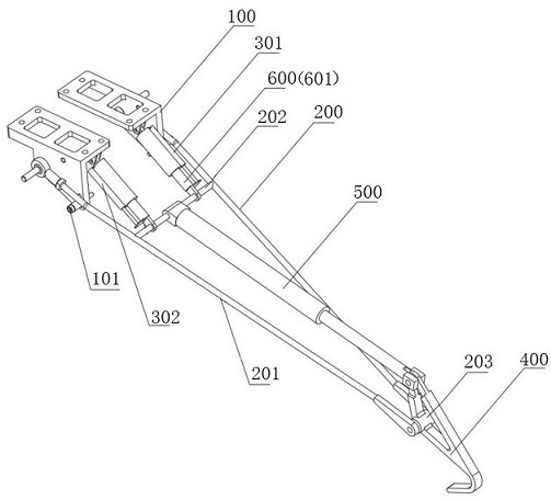
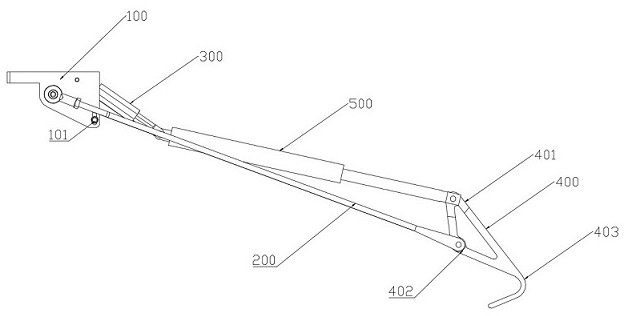
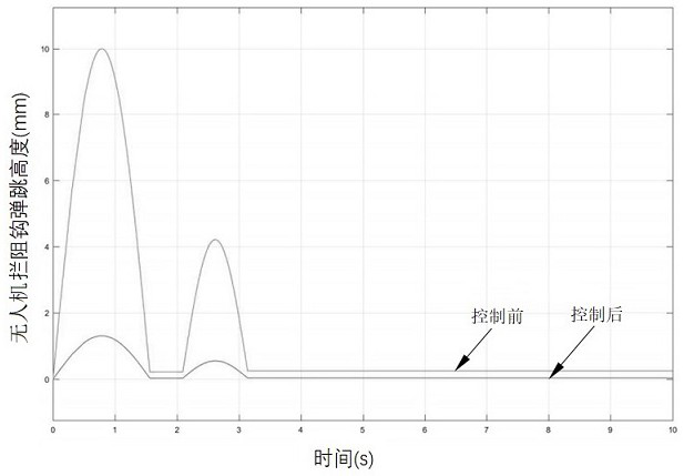
The invention provides an unmanned aerial vehicle arresting hook, a control method and an unmanned aerial vehicle. The unmanned aerial vehicle arresting hook includes a fixed support, a rotating support, and a first telescopic assembly, which are arranged on the fixed support, the arresting hook body, and the second telescopic assembly. component, sensor component, control component; the control component is configured to receive the deformation data of the first telescopic component sent by the sensor component, and send an instruction signal for controlling the action of the first telescopic component or the second telescopic component. The invention suppresses the bouncing of the UAV arresting hook through the joint action of the sensor assembly and the first telescopic assembly, so that the UAV arresting hook is within a relatively acceptable height range during the arresting process, and improves the success rate of the UAV hanging rope.

Description

technical field [0001] The invention relates to the technical field of unmanned aerial vehicle flying equipment, in particular to an arresting hook for an unmanned aerial vehicle, a control method and an unmanned aerial vehicle. Background technique [0002] With the continuous advancement of drone technology, the application fields and prospects of drones are constantly expanding. With the increase of drone application scenarios, the types of drones, whether military or civilian, are increasing. Fixed-wing, multi-rotor small and medium-sized, medium-sized, and some medium- and large-scale UAVs need ejection devices to shorten the take-off distance and also need arresting cables to shorten the landing run distance. The problem of resetting the UAV automatic decoupling device as soon as possible to prepare for the next landing has become increasingly prominent. At the moment when UAV cluster work is becoming more and more important, the recovery efficiency is an important fac...

Claims


Application Information

Patent Timeline
Patent Type & Authority Patents(China)
IPC IPC(8): B64C25/68
CPCB64C25/68
Inventor 彭一明郝嘉煜魏小辉聂宏张钊
Owner NANJING UNIV OF AERONAUTICS & ASTRONAUTICS
Why Eureka
Try Eureka