Normal pressure applying device

A technology of normal pressure and application device, applied in measuring device, measurement of elastic deformation force by measuring gauge, instrument, etc., can solve the problems of unstable normal pressure, reducing system compactness, circuit breakage, etc. Lateral play, elimination of relative wobble, effect of reducing the number of parts

Inactive Publication Date: 2013-05-08
BEIJING UNIV OF POSTS & TELECOMM
View PDF7 Cites 0 Cited by
  • Summary
  • Abstract
  • Description
  • Claims
  • Application Information

AI Technical Summary

Problems solved by technology

[0017] 1. In the dynamic contact resistance test, the normal pressure is unstable. In the case of sliding, because the surface of the contact and the sample is not absolutely smooth, there is a certain roughness, so when the contact slides relative to the sample, due to The stiffness of the spring is small, and the contact will jump due to the instantaneous upward impact, and the normal pressure applying device does not have a structure to inhibit the upward bounce of the contact, resulting in a sudden change in the size of the normal pressure, and the upward bounce of the contact Sometimes the circuit between the contact and the sample will be broken, resulting in a sudden change in the experimental data;
[0018] 2. The lateral gap of the structure has not been eliminated, and it cannot resist the lateral shear force. The guide post and the linear bearing are a transition fit, and there is a gap between them. In the case of large reciprocating motion such as sliding, the guide post will periodically The impact on the linear bearing will affect the experimental accuracy of the equipment after a long time;
[0019] 3. It is inconvenient to install the contacts. If the contacts are installed directly, they cannot be insulated from the mechanical system. In the experiment, in order to insulate the contacts and the contact clamping structure (contact fixture 107), the contacts will be put into a plastic tube , and then insert it into the contact fixture as a whole. This process requires a large force, and if the force is too large, it will cause the plastic tube to rupture, which will cause the contact and the contact fixture to lose their insulation, which will lead to the experiment. s failure
[0027] 1. The overall size of the structure is too large, which reduces the compactness of the entire system. If multi-channel experiments need to be carried out at the same time, this structure will be difficult to arrange due to the excessive size of the structure, which reduces the scalability of the entire system;
[0028] 2. The normal pressure loaded in the dynamic contact resistance test experiment is unstable. When the contact slides relative to the sample, the stiffness of the spring is also small, and the contact will jump due to the instantaneous upward impact, resulting in the contact between the contact and the sample. There is an open circuit between the samples, which makes the experimental data inaccurate
[0029] 3. Contact installation is inconvenient

Method used


Image

  • Normal pressure applying device
  • Normal pressure applying device
  • Normal pressure applying device

Examples


Embodiment Construction

[0056] In order to make the object, technical solution and advantages of the present invention clearer, the present invention will be further described in detail below with reference to the accompanying drawings and examples.

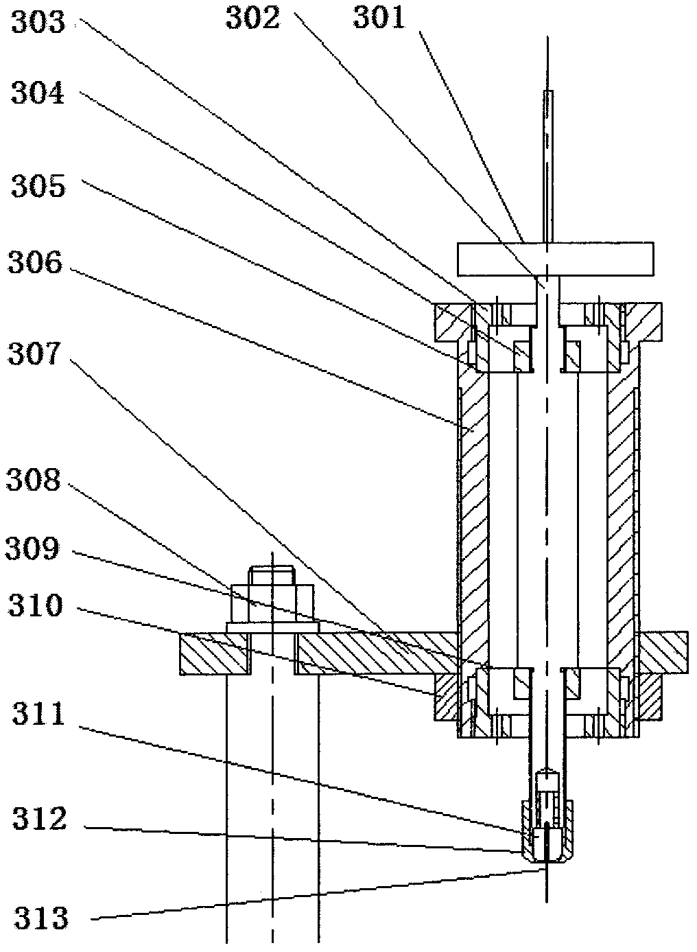
[0057] image 3 is a schematic cross-sectional structure of the normal pressure applying device of the present invention;

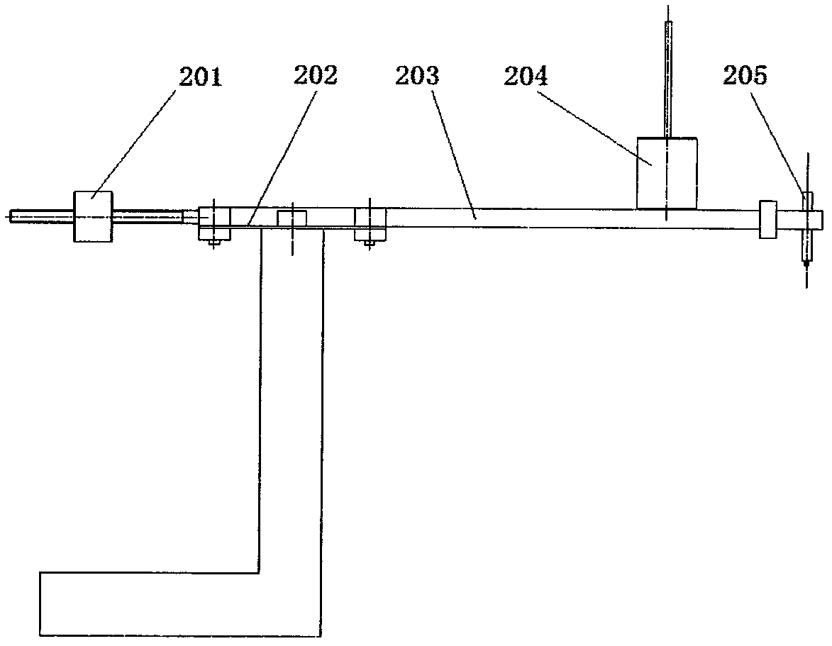
[0058] Figure 5 It is a schematic diagram of the three-dimensional structure assembled by the normal pressure applying device of the present invention;

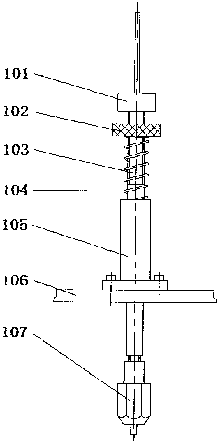
[0059] Figure 6 It is a schematic exploded view of the three-dimensional structure of the normal pressure applying device of the present invention. Such as image 3 , Figure 5 and Figure 6 As shown, the device includes: double-diaphragm spring and its fixing and positioning parts, central shaft and its fixing and positioning parts, contact fixing and positioning parts, sleeve and its locking parts. The parts are introduced as follows:

[0060] The double-diaphragm sprin...


PUM


Abstract

The invention discloses a normal pressure applying device, which comprises a dual-membrane spring and a fixing and positioning device thereof, a central shaft and a fixing and positioning component thereof, a contact fixing and positioning component, and a sleeve and a locking component thereof, wherein the dual-membrane spring and the fixing and positioning device thereof comprise an upper membrane spring, a lower membrane spring and a hold-down ring; the hold-down ring is connected with the sleeve through a screw thread; the central shaft and the fixing and positioning component thereof comprise a central shaft, an upper hold-down nut and a lower hold-down nut; the central shaft passes through the inner hole of each membrane spring; each hold-down nut is matched with the central shaft through a screw thread; the contact fixing and positioning component comprises a contact claw assembly I and a contact claw assembly II; the contact claw assembly I is connected with the central shaft through a screw thread; the contact claw assembly II can be extruded by rotating the contact claw assembly I; the sleeve and the locking component thereof comprise a sleeve, a support plate and a locking nut; and the sleeve is connected with the support plate and the locking nut through a T-shaped screw thread. Due to the adoption of the normal pressure applying device, the influence of lateral shearing force on an experimental result in an experiment can be greatly reduced, the applying accuracy of normal pressure is increased, and the compactness and the stability of the device are increased.

Description

technical field [0001] The invention relates to the field of weak electric contact testing, in particular to a normal pressure applying device. Background technique [0002] Electrical contacts widely exist in electronic and power systems, and reliable electronic connections are required between components, between circuits, between devices and even within components. There is contact resistance between two electronically connected components. The factors affecting contact resistance mainly include contact spot shape, contact form, contact pressure, temperature, pollution, contact surface finish, conductor material properties, surface coating, etc. [0003] Among them, the contact pressure is an important factor. Without sufficient pressure, the contact resistance cannot be significantly reduced just by increasing the size of the contact surface. [0004] Contact resistance includes shrinkage resistance and film resistance. When the contact pressure F is increased and the ...

Claims


Application Information

Patent Timeline
Patent Type & Authority Patents(China)
IPC IPC(8): G01L1/04G01R27/02
Inventor 周怡琳刘利彪许良军
Owner BEIJING UNIV OF POSTS & TELECOMM
Why Eureka
Try Eureka