Weft yarn measuring and storing device of loom

一种纬纱测长、储纱的技术,应用在织机、纺织、纺织品和造纸等方向,能够解决橡胶寿命降低等问题

Active Publication Date: 2017-06-30
TOYOTA IND CORP
View PDF6 Cites 0 Cited by
  • Summary
  • Abstract
  • Description
  • Claims
  • Application Information

AI Technical Summary

Problems solved by technology

If the spring force is strengthened to increase the pressing force of the pressure roller, the life of the rubber will be extremely reduced, and the pressure roller with a structure integrated with the rubber must be replaced frequently.

Method used


Image

  • Weft yarn measuring and storing device of loom
  • Weft yarn measuring and storing device of loom
  • Weft yarn measuring and storing device of loom

Examples


no. 1 Embodiment approach

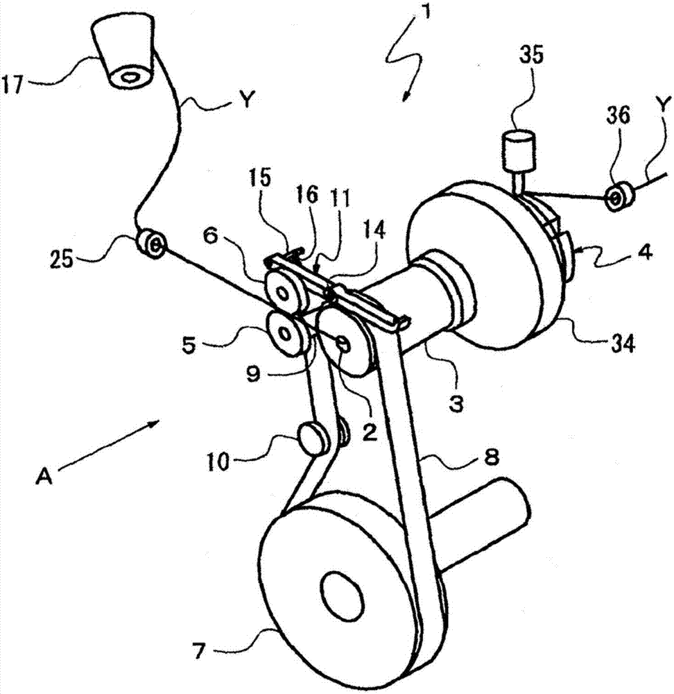
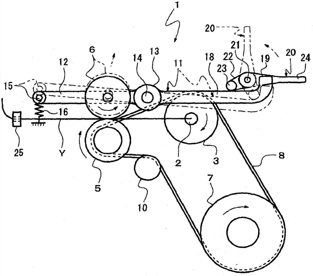
[0023] based on Figure 1 ~ Figure 3 The first embodiment will be described. exist figure 1 as well as figure 2 Among them, the weft yarn length measuring and storage device 1 provided on the loom has: a rotating shaft 3 having a weft yarn introduction port 2; a yarn storage cylinder 4 which is held on the front end side of the rotating shaft 3 in a stationary state; and a driving roller 5 and The feed rollers 6 are arranged parallel to the rotation shaft 3 . A pulley 7 is arranged below the rotating shaft 3, and the pulley 7 is connected to a main shaft (not shown) of the loom or a dedicated electric motor (not shown) to rotate.

[0024] The driving belt 8 wound around the pulley 7 is wound around the rotating shaft 3 , the shaft 9 of the driving roller 5 , and the guide roller 10 . The driving belt 8 can be constituted by a timing belt, a flat belt, or the like. When the pulley 7 rotates, the rotating shaft 3 and the driving roller 5 are rotated by the driving belt 8 ,...

no. 2 Embodiment approach

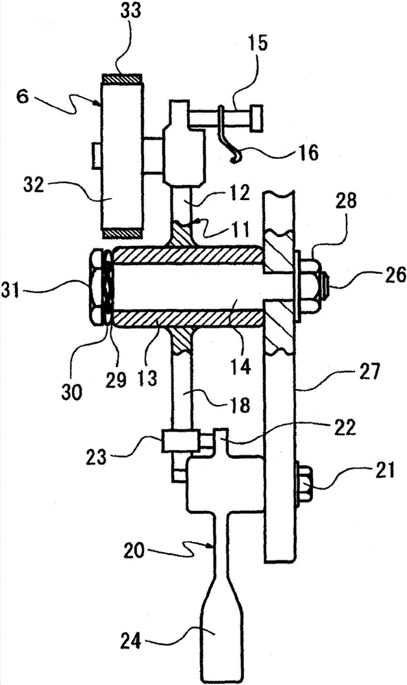
[0038] Figure 4 The second embodiment is shown, and the same configurations as those of the first embodiment will be described using the same reference numerals, and detailed description will be omitted. In the second embodiment, the frictional resistance applying portion is constituted by the coil spring 37 which is an elastic member. The coil spring 37 is fitted to the support shaft 14 protruding toward the end surface 29 side of the protruding portion 13 of the support rod 11 . After the coil spring 37 is fitted in the support shaft 14 , it is crimped to the end surface 29 of the protrusion 13 by fastening with the bolt 31 .

[0039] In the second embodiment, since the frictional resistance is added to the end surface 29 of the protrusion 13 by the spring force of the coil spring 37 interposed between the support rod 11 and the bolt 31, frictional resistance against the spring force of the spring 16 can be absorbed. The upward pressing force of the feed roller 6 suppress...

no. 3 Embodiment approach

[0041] Figure 5 3rd Embodiment is shown, and the same structure as 1st Embodiment is demonstrated using the same code|symbol, and detailed description is abbreviate|omitted. In the third embodiment, a frictional resistance applying portion is constituted by a cylindrical member 38 fixed to an outer peripheral surface 39 of a support shaft 14 . The cylindrical member 38 is fitted and fixed to the outer peripheral surface 39 of the support shaft 14 which is a contact portion with the support rod 11 . The outer periphery of the cylindrical member 38 is roughened so that the frictional resistance is increased by using processing techniques such as plating, shot peening, and shot peening.

[0042] The inner peripheral surface 40 of the protruding portion 13 of the support rod 11 , which is a contact portion with the support shaft 14 , is rotatably fitted to the cylindrical member 38 of the support shaft 14 , and is integrated with the support shaft 14 by fastening with the bolt 3...


PUM


Abstract

The invention provides a weft yarn measuring and storing device of a loom. The bounce of the feeding roller of the weft yarn measuring and storing device during the operation of the loom is inhibited without increasing the replacement frequency of the pressing roller. An end part of a bearing shaft 14 protruded from an end surface 29 of a supporting rod 11 is embedded with a waveform gasket 30 provided with a friction resistance applying part. The waveform gasket 30 is fixedly disposed on an end surface 29 of a protrusion part 13 in a crimping manner by a bolt 31. The waveform gasket 30is used to apply the friction resistance of the rotation with respect to the supporting rod 11 to the supporting rod 11. The upward thrusting pressure generated during bounce of a feeding roller 6 in the operation of the loom is absorbed by the friction resistance between the waveform gasket 30 and the end surface 29 of the protrusion part 13 of the supporting rod 11, and the generating of the bounce of the feeding roller 6 is inhibited.

Description

technical field [0001] The invention relates to a weft yarn length measuring yarn storage device in a loom. Background technique [0002] For example, Patent Document 1 discloses a weft yarn length measuring and storage device including a roller mechanism for transporting a weft yarn from a yarn supplying section to a yarn storage drum. The weft yarn length measuring yarn storage device of Patent Document 1 includes a rotating drum. An annular yarn storage portion is formed at one end of the drum, and an annular length measuring portion is formed at the other end. The pressure roller is pressed and connected to the length measuring part by the spring, and the pressure roller rotates driven by the rotation of the length measuring part. [0003] The weft yarn in the yarn feeding section is sandwiched between the rotating press roller and the length measuring section, and sent out toward the yarn storage section. The sent weft yarn is wound on the yarn storage part by the ac...

Claims


Application Information

Patent Timeline
Patent Type & Authority Applications(China)
IPC IPC(8): D03D47/36
CPCD03D47/363D03D47/36D03D47/30D03D47/362
Inventor 山内康史岛崎春雄垣内夏树
Owner TOYOTA IND CORP
Why Eureka
Try Eureka