Independent transmission lifting mechanism of spinning frame

An independent transmission and lifting mechanism technology, applied in textiles and papermaking, etc., can solve problems such as unstable yarn tension, reduced spinning efficiency, and inability to realize variable range and step-up movement of the yarn guide plate

Pending Publication Date: 2021-07-30
HUBEI TIANMEN TEXTILE MACHINERY
View PDF0 Cites 0 Cited by
  • Summary
  • Abstract
  • Description
  • Claims
  • Application Information

AI Technical Summary

Problems solved by technology

But there are still some defects: since the up and down movement of the yarn guide plate and the ring plate are not driven separately, the range-changing and step-up movement of the yarn guide plate cannot be realized. The problem of too small ring c...

Method used


Image

  • Independent transmission lifting mechanism of spinning frame
  • Independent transmission lifting mechanism of spinning frame
  • Independent transmission lifting mechanism of spinning frame

Examples


Embodiment Construction

[0033] In order to make the purpose, technical solution and advantages of the present invention clearer, the embodiments of the present invention will be further described below in conjunction with the accompanying drawings.

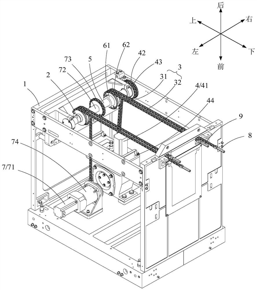
[0034] See figure 2 , the embodiment of the present invention provides an independent transmission and lifting mechanism for spinning frames, including a headstock frame 1, a rotating shaft 2, a ring plate connector 3, a ring plate drive mechanism 4, a rotating cylinder 5, and a yarn guide plate connector 6 And the yarn guide plate driving mechanism 7.

[0035] The rotating shaft 2 extends along the left and right directions, and is axially rotatable and installed on the head frame 1; the upper end of the ring plate connector 3 is flexible, wound on the rotating shaft 2, and fixedly connected with the rotating shaft 2, and the lower end Used for fixed connection with the ring plate, in this embodiment, the lower end is fixedly connected with the ring p...


PUM


Abstract

The invention provides an independent transmission lifting mechanism of a spinning frame. A rotating shaft extends in the left-right direction and can be installed on a headstock rack in an axial rotation mode; the upper end of a steel collar plate (ring plate) connecting piece is flexibly arranged, is wound on the rotating shaft and is fixedly connected with the rotating shaft; a steel collar plate driving mechanism drives the rotating shaft to axially rotate so as to drive a steel collar plate to move up and down; the left end and the right end of a rotating cylinder are opened and coaxially arranged on the periphery of the rotating shaft in a sleeving mode; the upper end of a yarn guide plate connecting piece is flexibly arranged, is wound on the rotating cylinder and is fixedly connected with the rotating cylinder; and a yarn guide plate driving mechanism drives the rotating cylinder to axially rotate so as to drive a yarn guide plate to move up and down. The technical scheme provided by the invention has the beneficial effects that the yarn guide plate ascends and descends relative to the steel collar plate in a variable range, and the size of a ballooning convex shape can be adjusted in the whole spinning process, so that the yarn tension is adjusted, the proper yarn tension is kept, and the variable range upgrading of the yarn guide plate relative to the steel collar plate in the whole spinning process is realized on the premise that yarns are not broken; and therefore, high-speed spinning in the whole process is achieved.

Description

technical field [0001] The invention relates to the technical field of spinning frames, in particular to an independent transmission and lifting mechanism of spinning frames. Background technique [0002] The winding forming part is one of the important parts on the spinning frame. It has a great influence on the spinning end breakage, winding and unwinding efficiency, and is closely related to improving product quality, saving cotton and reducing the labor intensity of operators. [0003] The winding and forming parts of the traditional spinning frame generally adopt the mechanical forming mechanism of forming cam and swing arm and three automatic upgrading devices. The lifting and reciprocating motion of the ring plate and the yarn guide plate is to rely on the cam (21) to act on the wheel (22) on the swing arm (23) to force the main traction chain (24) to pull the distribution shaft (25) back and forth to rotate, and then the chain wheel Drive the ring plate lifting rod ...

Claims


Application Information

Patent Timeline
IPC IPC(8): D01H13/10
CPCD01H13/104
Inventor 沈方勇杜亚杰吴阳沈忱
Owner HUBEI TIANMEN TEXTILE MACHINERY
Why Eureka
Try Eureka