
Prestressed anchor bolt mounting structure and mounting method

A technology of installation structure and installation method, applied in infrastructure engineering, construction and other directions, can solve problems such as hidden safety hazards of anchor bolts

Pending Publication Date: 2021-07-30
HUADIAN HEAVY IND CO LTD
View PDF0 Cites 0 Cited by
  • Summary
  • Abstract
  • Description
  • Claims
  • Application Information

AI Technical Summary

Problems solved by technology

[0005] Therefore, the technical problem to be solved by the present invention is to overcome the defects in the prior art that are prone to safety hazards during the anchor bolt installation process.

Method used


Image

  • Prestressed anchor bolt mounting structure and mounting method
  • Prestressed anchor bolt mounting structure and mounting method

Examples


Embodiment 1

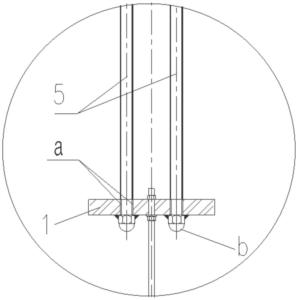
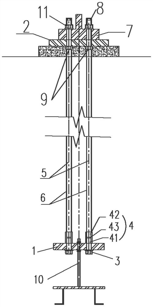
[0034] This embodiment provides a prestressed anchor bolt installation structure, such as figure 2 shown, including:

[0035] The lower anchor plate 1 is provided with a plurality of first through holes;

[0036] The upper anchor plate 2 is set corresponding to the lower anchor plate, and the upper anchor plate 2 is correspondingly provided with a plurality of second through holes;

[0037] Specifically, the upper anchor plate 2 and the lower anchor plate 1 extend along the horizontal direction, so as to play a stabilizing action in concrete. Meanwhile, the upper anchor plate 2 and the lower anchor plate 1 are made of technical materials, such as steel, respectively. The shapes of the first through hole and the second through hole are not limited, and their function is to realize the connection action. In this embodiment, as figure 2 As shown, the first through hole is arranged below the second through hole, and the first through hole and the second through hole are arran...

Embodiment 2

[0058] This embodiment provides a method for installing prestressed anchor bolts, including the following steps:

[0059] Install the threaded sleeve 4 and the bottom bolt 3 on the lower anchor plate 1, so that the bottom bolt 3 is connected to one end of the threaded sleeve 4 through the lower anchor plate 1;

[0060] One end of the anchor bolt 5 is connected to the upper anchor plate 2, and the other end is connected to the other end of the threaded sleeve 4 to form 5 anchor bolt frames;

[0061] Concrete is poured on the 5 anchor bolts, and the concrete is poured to the position below the upper anchor plate 2.

[0062] When the anchor bolt 5 breaks, the upper anchor bolt 5 is taken out, and then the remaining anchor bolt 5 heads are removed from the threaded sleeve 4 by a spark machine, and the complete anchor bolt is installed on the On the threaded sleeve 4.

[0063] After pouring the concrete, the figure 2 As shown, the position of the concrete will extend to the bot...


PUM


Abstract

The invention provides a prestressed anchor bolt mounting structure and a mounting method. A first through hole is formed in a lower anchor plate, then a threaded sleeve is mounted on the lower anchor plate through a bottom bolt, and the threaded sleeve can be connected with an anchor bolt at the same time. Through the arrangement mode, the mounting operation of the anchor bolt is achieved, and meanwhile the situation that damage is caused to the lower anchor plate when the anchor bolt is connected on the lower anchor plate in a welding mode, and then adverse effects are caused to the overall structure in the prior art can be avoided; at the same time, by arranging the threaded sleeve, the situation that concrete enters the first through hole of the lower anchor plate can be prevented, and therefore sealing treatment does not need to be conducted on gaps during concrete pouring; more importantly, as the threaded sleeve completely enters the concrete after being poured, the bottom bolt is as strong as the anchor bolt at the moment, so that the broken position of the anchor bolt is ensured to be in the threaded sleeve or above the threaded sleeve, and replacement of the anchor bolt is facilitated at the moment.

Description

technical field [0001] The invention relates to the technical field of engineering construction, in particular to a prestressed anchor bolt installation structure and an installation method. Background technique [0002] The structure of anchor bolts is widely used in the field of engineering construction. By setting anchor bolts during the construction process, the connection strength can be effectively improved. [0003] On cap foundations such as wind power plants, prestressed anchor bolts are usually installed. The lower part of the prestressed anchor bolts sinks below the cap foundation, and the upper part is exposed to the outside through the concrete of the cap foundation. In the prior art, the strength of the anchor bolt itself is relatively high, and generally it will not break. However, if a fracture must occur, the replacement work will be very complicated. Generally speaking, in order to remove the broken anchor bolt in the foundation of the cap, the concrete at...

Claims


Application Information

Patent Timeline
Patent Type & Authority Applications(China)
IPC IPC(8): E02D27/42
CPCE02D27/42E02D27/425
Inventor 王怀明周兴华徐世宏彭刚平赵玉琢裴立勤王玉林刘玉飞孙臣王子陈冲赵辉张健翔董宏季
Owner HUADIAN HEAVY IND CO LTD
Learn More