Buffering device

A buffer device and buffer tube technology, applied in the direction of coil springs, shock absorbers, springs, etc., can solve the problems of poor vibration reduction effect and low specific damping coefficient, and achieve good energy dissipation effect, large specific damping coefficient, The effect of good mechanical properties and energy dissipation capacity

Active Publication Date: 2021-07-30
HARBIN INST OF TECH
View PDF14 Cites 0 Cited by
  • Summary
  • Abstract
  • Description
  • Claims
  • Application Information

AI Technical Summary

Problems solved by technology

However, like other negative stiffness structures, the sleeve-type negative stiffness structure has a wave-like undulating load-displacement curve, so its specific damping coefficient is not high, and the vibration reduction effect is not good

Method used


Image

  • Buffering device
  • Buffering device
  • Buffering device

Examples


example 1

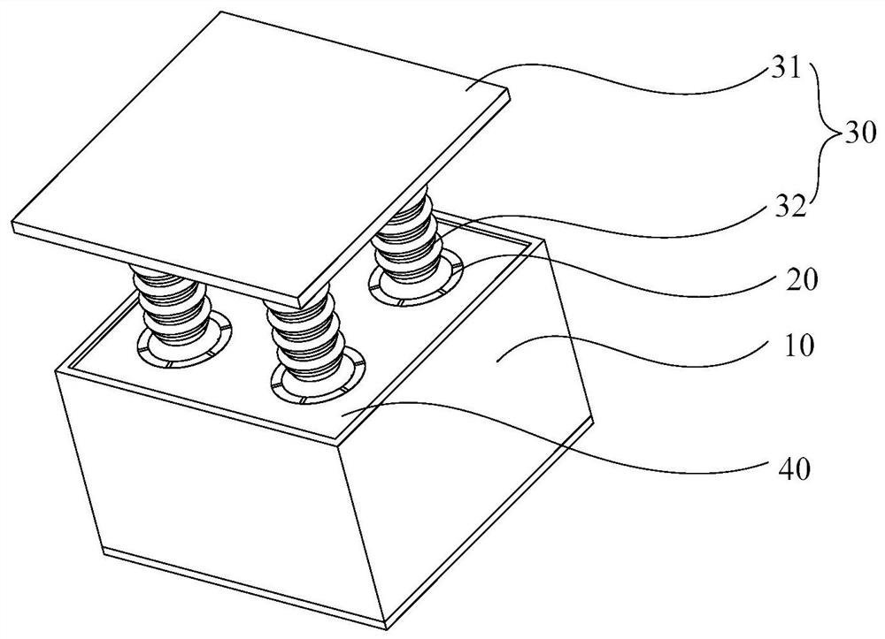
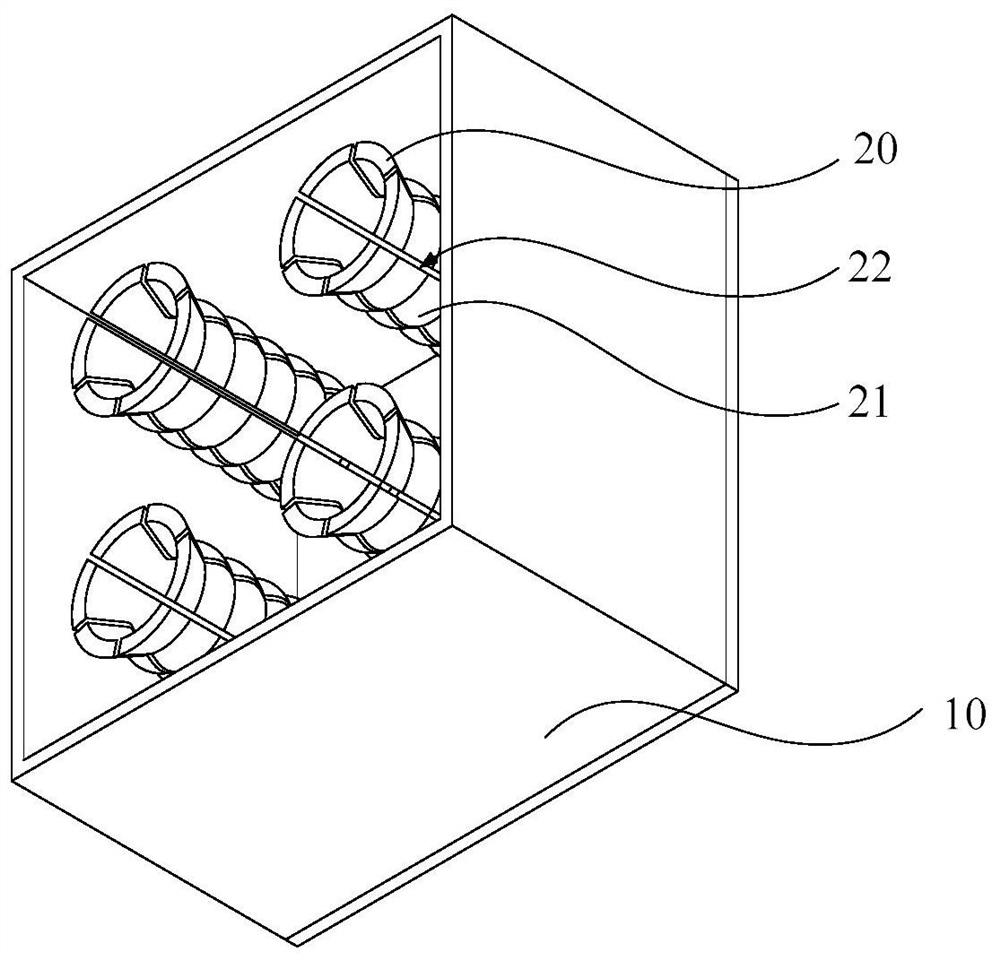
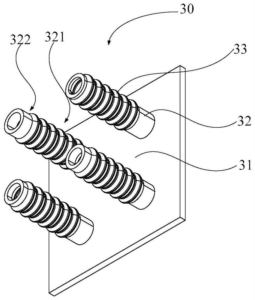
[0075] The buffer device includes: housing 10, four buffer tube 20, support member 30, elastic portion 40, and a resilient support. The support 30 includes four support columns 32 and support plates 31, and the length of the four support post 32 is four, and the length of the support tail section 322 is 5 mm, 3.75 mm, 2.5 mm, 1.25 mm, respectively. The phase difference between the support tail section 322 is 1.25 mm. This buffer device is from 1 to 2-3-4 structures.

example 2

[0077]The buffer device includes: housing 10, four buffer tube 20, support member 30, elastic portion 40, and a resilient support. The support member 30 includes four support columns 32 and support plates 31, and the length of the four support posts 32 is two, and the length of the support tail section of the two support post 32 is different, and the support tail section 322 The length is 5 mm, 2.5 mm, respectively. The phase difference between the support tail section 322 is 2.5 mm. The buffer device is from 1 to 3-1-3 structures.

[0078] Contrast 1

[0079] The buffer device includes a housing 10, a buffer tube 20, a support member 30, an elastic portion 40, and an elastic support. The support member 30 includes a support post 32 and a support plate 31 that support the support post 32 of 5 mm. This buffer device is a single cell structure

[0080] Contrast 2

[0081] The buffer device includes: housing 10, four buffer tube 20, support member 30, elastic portion 40, and a resili...


PUM


Abstract

The invention provides a buffering device. The buffering device comprises a shell, a plurality of buffering pipes, an elastic part, a supporting piece and an elastic supporting part; a plurality of similar annular grooves are formed in the hole walls of the buffering pipes, and a plurality of gaps formed in the axial directions of the buffering pipes are formed in the buffering pipes; the elastic part is arranged in the accommodating cavity; a plurality of ring-like bulges are arranged on the outer wall surface of each supporting column; the elastic supporting part is arranged in a connecting hole and located between the shell and the supporting columns; each supporting column comprises a connecting section, a protruding section and a supporting tail section which are sequentially connected; and the lengths of the supporting tail sections of the multiple supporting columns are at least two. According to the buffering device, due to the fact that the lengths of the supporting tail sections in the supporting columns are different, the protruding sections on the different supporting columns have phase differences; the resistances borne by the different supporting columns are different; therefore the load-displacement curve of the structure is changed through the combination of the different supporting columns; and the specific damping coefficient of the buffer device is greatly improved to enhance the buffering performance of the structure.

Description

Technical field [0001] The present application relates to the field of vibration damping technology, and more particularly to a buffer device. Background technique [0002] Negative strength multi-steady-state structures are often used in damping damping related fields. The study is more relatively negative structural structure of the beam / shell. The existing sleeve negative structure is more excellent in mechanical properties with respect to the beam-type negative structure, and more energy can be absorbed under the same quality. Moreover, such structures do not rely on viscoelastic or viscous to carry out energy absorption because there is also a good suction effect in low frequency / low speed. However, like other negative structures, the sleeve-type negative stiffness structure has a wavelet load displacement curve, which is not high than the damping coefficient, and the damping effect is not good. Inventive content [0003] The purpose of this application is to provide a ...

Claims


Application Information

Patent Timeline
Patent Type & Authority Applications(China)
IPC IPC(8): F16F15/02F16F15/04F16F15/08
CPCF16F15/02F16F15/03F16F15/046F16F15/085F16F2222/04F16F2222/06F16F2238/02F16F2238/026
Inventor 王兵朱绍伟陈帅连续
Owner HARBIN INST OF TECH
Why Eureka
Try Eureka