
Large-stroke impact buffering device and impact crushing equipment

An impact buffering, large stroke technology, applied in mechanical equipment, vibration suppression adjustment, grain handling, etc., can solve the problems of equipment damage, the impact force cannot be too large, and the tension of the wire rope is increased, so as to achieve the life of the hoisting device and the safety of use. sexual effect

Active Publication Date: 2021-07-30
CHINA RAILWAY ENG MASCH RES & DESIGN INST CO LTD
View PDF6 Cites 0 Cited by
  • Summary
  • Abstract
  • Description
  • Claims
  • Application Information

AI Technical Summary

Problems solved by technology

During the impact process, the greater the impact stroke, the better the rock-breaking effect. However, due to the greater the falling stroke during the impact, the greater the tension of the wire rope on the equipment, or the occasional empty smashing of the equipment due to other reasons, the wire rope The pulling force will also be greatly increased
The current equipment is often limited by insufficient cushioning, and the impact force of the drop should not be too large, otherwise it is easy to cause damage to the equipment

Method used


Image

  • Large-stroke impact buffering device and impact crushing equipment
  • Large-stroke impact buffering device and impact crushing equipment
  • Large-stroke impact buffering device and impact crushing equipment

Examples


Embodiment Construction

[0032] In order to make the above objects, features and advantages of the present invention more comprehensible, specific embodiments of the present invention will be described in detail below in conjunction with the accompanying drawings.

[0033] In the description of the present invention, it should be understood that the orientation or positional relationship indicated by the terms "upper", "lower", "front", "rear", "left", "right" etc. are based on those shown in the accompanying drawings. Orientation or positional relationship is only for the convenience of describing the present invention and simplifying the description, and does not indicate or imply that the referred device or element must have a specific orientation, be constructed and operated in a specific orientation, and thus should not be construed as a limitation of the present invention.

[0034] Moreover, the Z axis in the accompanying drawings represents the vertical direction, that is, the up and down positi...


PUM


Abstract

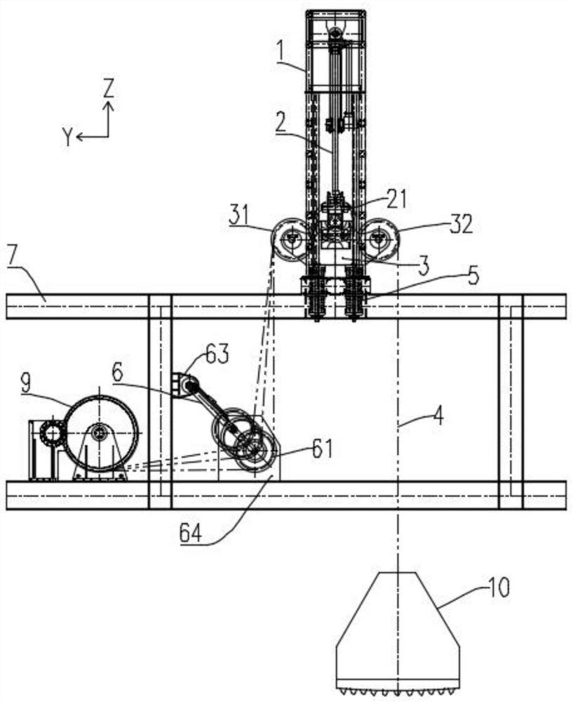
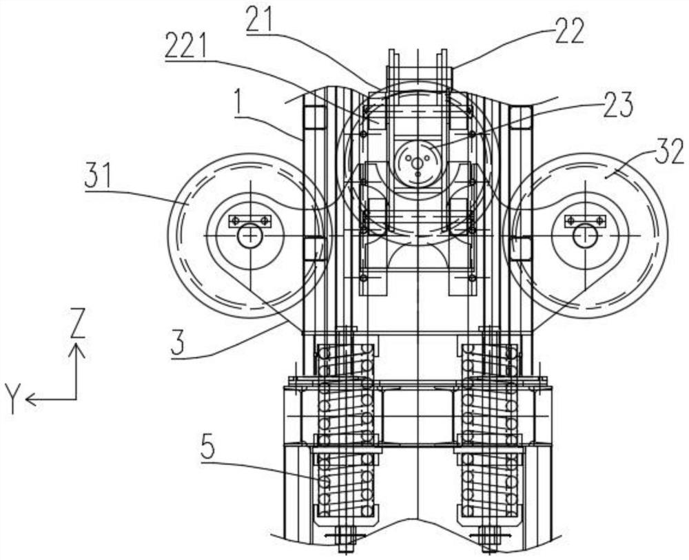
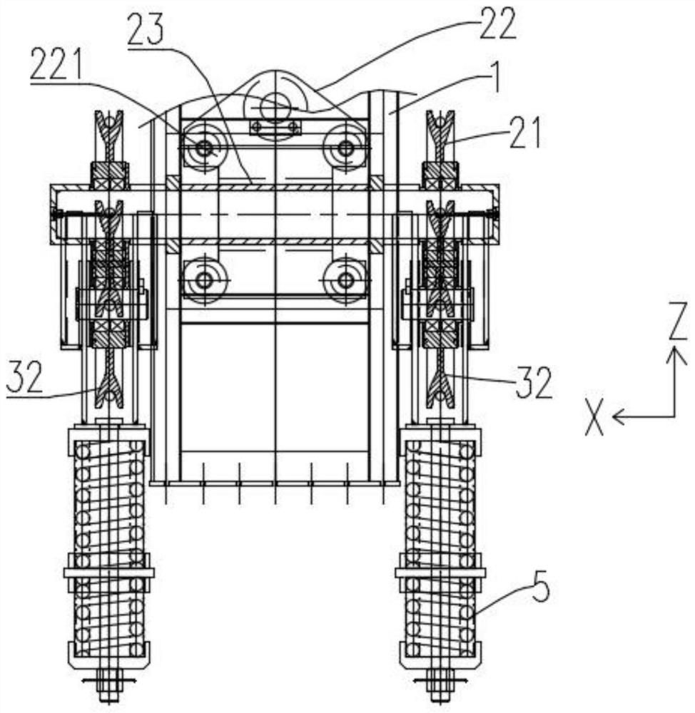
The invention provides a large-stroke impact buffering device and impact crushing equipment, and belongs to the technical field of geotechnical engineering. The large-stroke impact buffering device comprises a bottom frame, a buffer oil cylinder, a winding device, a tower, an impact oil cylinder, a support and a rope strip. One end of the buffer oil cylinder is connected with the bottom frame, the other end of the buffer oil cylinder is connected with a first guide pulley, an overflow valve is arranged on the buffer oil cylinder, the winding device is arranged on the bottom frame, the tower is arranged on the top of the bottom frame, the top end of the impact oil cylinder is connected with the top of the tower, and a second guide pulley is arranged at the bottom end of the impact oil cylinder. The bottom of the support is connected with the top of the bottom frame through a buffer spring, the support is located below the second guide pulley, one end of the rope strip is connected with the winding device, and the other end of the rope strip sequentially passes through the first guide pulley and the second guide pulley and then is connected with an impact hammer. When the pressure of the rope strip on the first guide pulley is larger than a preset value, the overflow valve is opened to enable the buffer oil cylinder to contract. The buffer effect during rock breaking impact is improved.

Description

technical field [0001] The invention relates to the technical field of geotechnical engineering, in particular to a large stroke impact buffer device and impact crushing equipment. Background technique [0002] In geotechnical engineering, trenching and trenching are often required, and impact equipment is most effective for hard rock construction. During the impact process, the greater the impact stroke, the better the rock-breaking effect. However, due to the greater the falling stroke during the impact, the greater the tension of the wire rope on the equipment, or the occasional empty smashing of the equipment due to other reasons, the wire rope The pulling force will also be greatly improved. The current equipment is often limited by insufficient cushioning, and the impact force of the drop cannot be too large, otherwise it is easy to cause damage to the equipment. Contents of the invention [0003] The invention aims at improving the cushioning effect during rock-br...

Claims


Application Information

Patent Timeline
Patent Type & Authority Applications(China)
IPC IPC(8): F16F15/067F16F15/023B02C19/00
CPCF16F15/067F16F15/023B02C19/00Y02E10/72
Inventor 高大诚李遥陶海洋万正伟宋波骆宇恒郑泽林
Owner CHINA RAILWAY ENG MASCH RES & DESIGN INST CO LTD
Learn More