
Pneumatic pipe connector and using method thereof

A technology of pneumatic tubes and inner tubes, applied in the direction of pipes/pipe joints/fittings, pipes, branch lines, etc., which can solve problems such as affecting use, falling off of pneumatic tubes, and inability to independently adjust fluid flow

Active Publication Date: 2021-07-30
深圳市伙伴气动精密机械有限公司
View PDF10 Cites 0 Cited by
  • Summary
  • Abstract
  • Description
  • Claims
  • Application Information

AI Technical Summary

Problems solved by technology

[0004] The object of the present invention is to provide a pneumatic pipe joint, which solves the problem that when the existing pneumatic pipe joint is in use, when the joint is fixed on the wall or other planes, Just can't adjust the interface direction, it is inconvenient to install the pneumatic tube; when the existing pneumatic tube joint is in use, the connection between the pneumatic tube and the joint is unstable, and the pneumatic tube is easy to fall off from the joint, which affects the use; the existing pneumatic tube joint is in use When in use, the technical problem of not being able to independently adjust the fluid flow through a single interface

Method used


Image

  • Pneumatic pipe connector and using method thereof
  • Pneumatic pipe connector and using method thereof
  • Pneumatic pipe connector and using method thereof

Examples


Embodiment Construction

[0030] The technical solutions of the present invention will be clearly and completely described below in conjunction with the embodiments. Apparently, the described embodiments are only some of the embodiments of the present invention, not all of them. Based on the embodiments of the present invention, all other embodiments obtained by persons of ordinary skill in the art without creative efforts fall within the protection scope of the present invention.

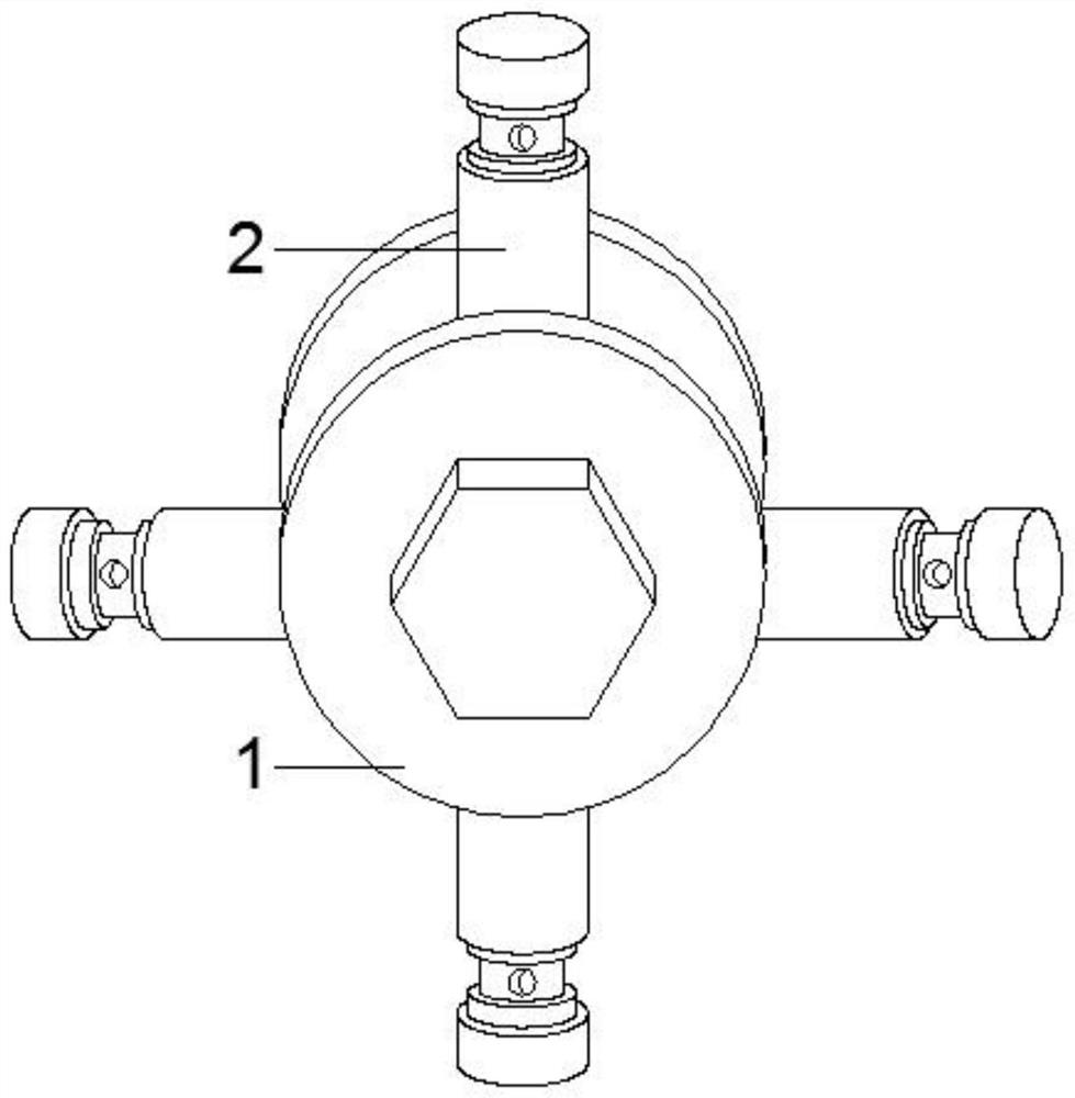
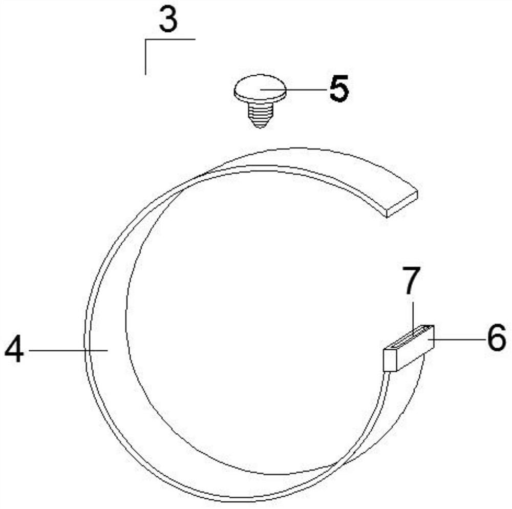
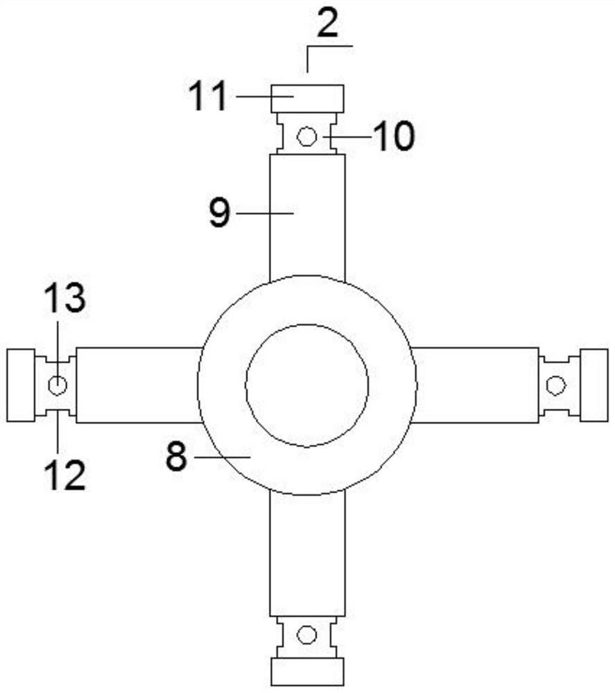
[0031] see Figure 1-7 As shown, a pneumatic pipe joint includes a steering mechanism 1, a connecting mechanism 2 and a fixing mechanism 3. The fixing mechanism 3 includes a fixing ring 4 and a fixing screw 5. One end of the fixing ring 4 is equipped with a ring sleeve 6, which passes through the ring sleeve The upper and lower ends of 6 are provided with slots 7 on one side, and the connecting pipe mechanism 2 includes a central ring pipe 8. Four interface branch pipes 9 are installed on the outside of the center ring pipe...


PUM


Abstract

The invention relates to pneumatic pipe connector. The pneumatic pipe connector comprises a direction adjusting mechanism, a pipe connecting mechanism and a fixing mechanism, the fixing mechanism comprises a fixing ring and a fixing screw, a ring sleeve is installed at one end of the fixing ring, inserting grooves are formed in the positions, close to one side, of the upper end and the lower end of the ring sleeve in a penetrating mode, the pipe connecting mechanism comprises a center ring pipe, and four connector branch pipes are installed on the outer side of the center ring pipe; and an adjusting inner pipe is arranged at the position, close to one end, in each connector branch pipe, a circle of annular groove is formed at the position, close to one end, of the periphery of each adjusting inner pipe, a fixing screw hole is formed at the position, located at the corresponding annular groove, of the front surface of each adjusting inner pipe, a sealing cover is arranged at the tail end of each adjusting inner pipe, and a flow limiting mechanism is arranged at the other end of each adjusting inner pipe. According to the pneumatic pipe connector, even if the pneumatic pipe connector is fixedly installed, the direction of the connector branch pipes can still be adjusted, a pneumatic pipe can be conveniently installed, and meanwhile, the stability of the connecting position of the pneumatic pipe and the connector is enhanced, the pneumatic pipe is prevented from being separated from the adjusting inner pipes, and the flow of fluid flowing through the four adjusting inner pipes can be independently adjusted.

Description

technical field [0001] The invention relates to the field of pneumatic pipe joints, in particular to a pneumatic pipe joint and its use method. Background technique [0002] Pneumatic pipe joint is a connection joint used to establish pneumatic pipe and pneumatic equipment. There are many types of pneumatic pipe joints, which can be divided according to the structure or the number of interfaces. It has the advantages of easy installation, strong pressure resistance and sealing performance. Good and other advantages. [0003] There are certain disadvantages in the use of the existing pneumatic pipe joints. When the existing pneumatic pipe joints are in use, when the joints are fixed on the wall or other planes, the direction of the interface cannot be adjusted, which is not convenient for the installation of the pneumatic pipes; When the pneumatic pipe joint is in use, the connection between the pneumatic pipe and the joint is unstable, and the pneumatic pipe is easy to fall...

Claims


Application Information

Patent Timeline
IPC IPC(8): F16L41/03F16L27/08
CPCF16L41/03F16L27/0812
Inventor 卢莹莹陈红梅贺瑞易雪明
Owner 深圳市伙伴气动精密机械有限公司
Learn More