Eureka AIR delivers breakthrough ideas for toughest innovation challenges, trusted by R&D personnel around the world.

Ripple-based redundant power supply current sharing state identification method

An identification method and technology of redundant power supply, applied in the direction of power supply testing, measuring current, measuring current/voltage, etc., can solve the problem of increasing hardware costs and limitations, the difficulty of monitoring a single power supply, and the inability to obtain single power supply status data, etc. problem, to achieve the effect of simplifying the hardware

Active Publication Date: 2021-07-30
UNIV OF ELECTRONICS SCI & TECH OF CHINA
View PDF13 Cites 3 Cited by
  • Summary
  • Abstract
  • Description
  • Claims
  • Application Information

AI Technical Summary

Problems solved by technology

Since the entire redundant power supply should be load-balanced during normal operation, long-term operation and aging will cause the workload of the redundant power supply to be unbalanced, and the frequency components in the power spectrum of the total ripple can reflect such an imbalance. relation
[0005] The traditional method is to obtain parameters such as current and voltage for a single power supply in a redundant structure and perform signal processing to determine the output of each power supply and monitor the status of the redundant structure, but this inadvertently increases hardware costs And limitations, for example, in a well-packaged redundant power supply, we cannot obtain the status data of a single power supply, and it is difficult to monitor a single power supply at this time

Method used


Image

  • Ripple-based redundant power supply current sharing state identification method
  • Ripple-based redundant power supply current sharing state identification method
  • Ripple-based redundant power supply current sharing state identification method

Examples


Embodiment

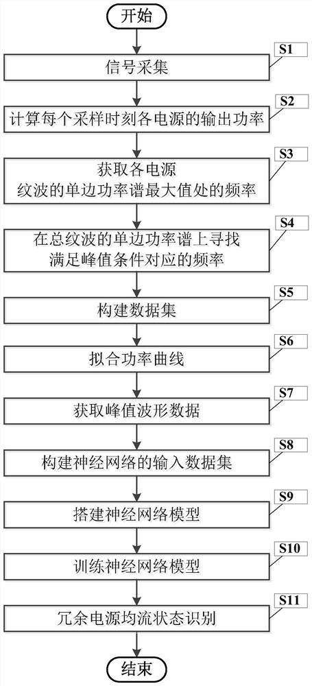
[0111] figure 1 It is a flowchart of a redundant power supply current sharing state identification method based on ripple in the present invention.

[0112] In this example, if figure 1 As shown, a kind of ripple-based redundant power current sharing state identification method of the present invention comprises the following steps:

[0113] S1, signal acquisition

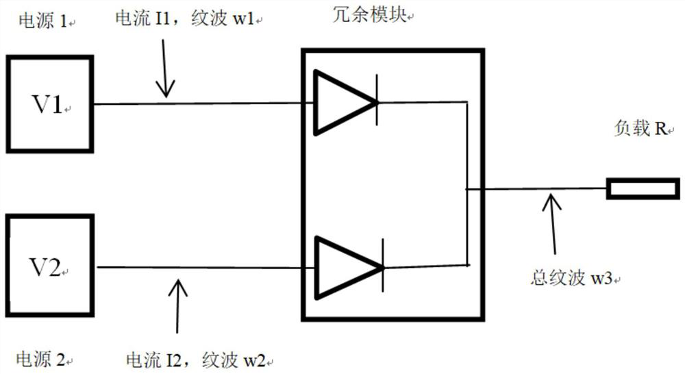
[0114] Such as figure 2 As shown, input 2 power supplies in parallel to the redundant module, and then collect the current I of each power output terminal at 16 sampling times i (t) and ripple W i (t), and the total ripple W(t) at the output of the redundant module, where, i=1,2,3, k represents the maximum number of the power supply, t=1,2,...,16;

[0115] S2. Calculate the output power P of each power supply at each sampling moment i (t);

[0116] P i (t)=(I i (t)) 2 R(t) (1)

[0117] Among them, R(t) represents the load resistance at the tth sampling moment;

[0118] In this embodiment, the actual po...


PUM


Abstract

The invention discloses a ripple-based redundant power supply current-sharing state identification method. The method comprises the following steps of firstly collecting current and ripple of each power supply at different moments and total ripple of an output end of a redundant module, and then calculating power and single-side power spectrum of each power supply at different moments and single-side power spectrum of the total ripple; then acquiring the frequency at the maximum value of the single-side power spectrum of each power supply ripple and the corresponding frequency meeting the peak condition on the single-side power spectrum of the total ripple; fitting of a power curve and building and training of a neural network model being carried out, a power supply label probability value tensor being predicted through a neural network, and then redundant power supply current sharing state identification being completed.

Description

technical field [0001] The invention belongs to the technical field of power supply state identification, and more specifically, relates to a method for identifying a current-sharing state of a redundant power supply based on ripple. Background technique [0002] Redundant power supply was originally used for server power supply. Because the server needs to work stably for a long time, and a sudden power failure may cause server data loss, so multiple power supplies are used to form a redundant power supply to supply power to the server. When a power supply is abnormal or stops When working, there will be other power supplies to supply power to the server to ensure that the server can always be powered. Nowadays, whether it is the power supply of computer motherboard or large-scale automatic control system, redundant power supply structure is used for power supply to ensure the stability of power supply during the operation of equipment and prevent unnecessary losses caused ...

Claims


Application Information

Patent Timeline
Patent Type & Authority Applications(China)
IPC IPC(8): G01R31/40G01R23/02G01R21/00G01R19/00
CPCG01R31/40G01R19/0092G01R21/00G01R23/02
Inventor 白利兵谢松林周权程玉华张杰陈聪田露露
Owner UNIV OF ELECTRONICS SCI & TECH OF CHINA
Why Eureka
Eureka Blog
Learn More