Yarn discharging and tube replacing integrated device

A technology of lower yarn and tube, applied in textiles and papermaking, etc., to achieve the effect of cost reduction, good rhythm and strong cohesion

Active Publication Date: 2021-08-03
WUHAN TEXTILE UNIV
View PDF10 Cites 2 Cited by
  • Summary
  • Abstract
  • Description
  • Claims
  • Application Information

AI Technical Summary

Problems solved by technology

[0006] The purpose of the present invention is to overcome the defects and problems existing in the prior art that the production efficiency cannot be improved by simplify...

Method used


Image

  • Yarn discharging and tube replacing integrated device
  • Yarn discharging and tube replacing integrated device
  • Yarn discharging and tube replacing integrated device

Examples


Embodiment 1

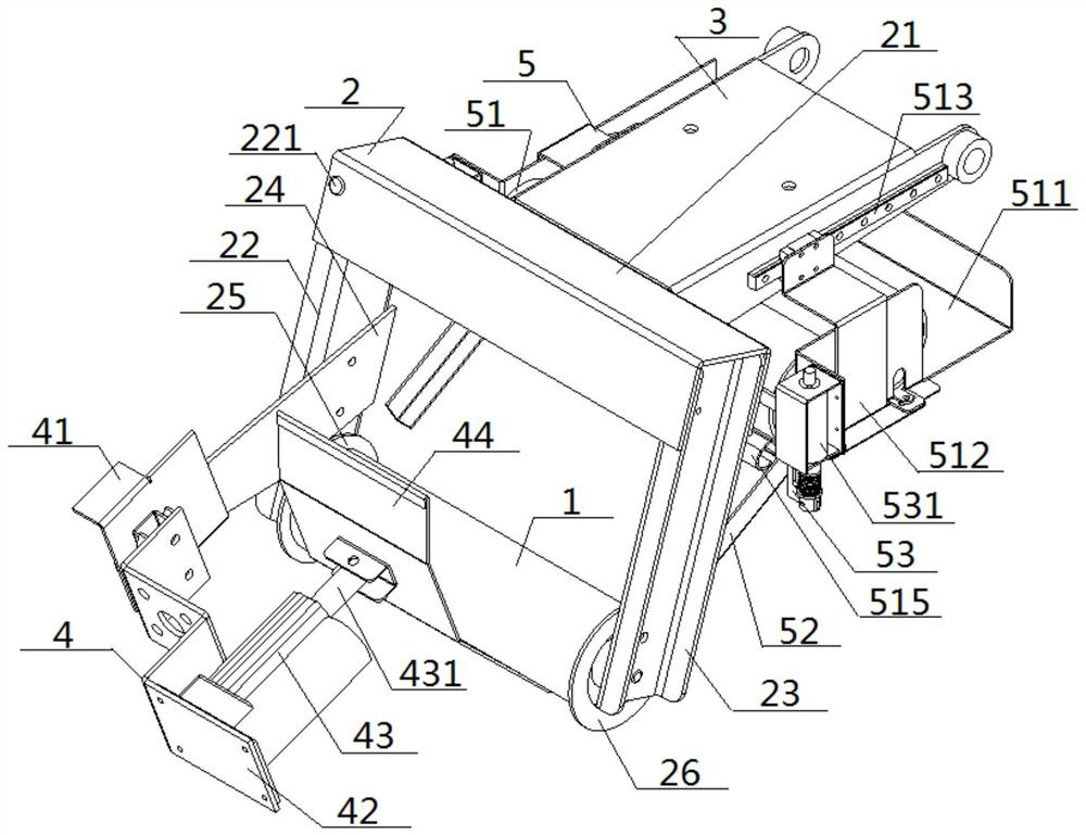
[0062] see figure 1 — Figure 8 , an integrated device for bobbin changing, comprising a winding bobbin clamp 2, a bobbin clamp connecting plate 3, a yarn lowering unit 4 and an empty tube storage unit 5, the winding bobbin clamp 2 includes a clamping top beam 21, a movable side The arm 22 is connected to the fixed side arm 23, the rear end of the clamping beam 21 is connected to the front end of the bobbin clamp connecting plate 3, and the two ends of the clamping beam 21 are respectively connected to the top of the movable side arm 22 and the fixed side arm 23. , the top of the movable side arm 22 is hinged with the top crossbeam 21, the bottom ends of the movable side arm 22 and the fixed side arm 23 are respectively provided with a movable insert 25 and a fixed insert 26, and the movable insert 22 is close to the movable insert. 25 is connected with the inner end of the oblique handle 24, and the outer end of the oblique handle 24 extends away from the movable side arm 22...

Embodiment 2

[0065] Basic content is the same as embodiment 1, the difference is:

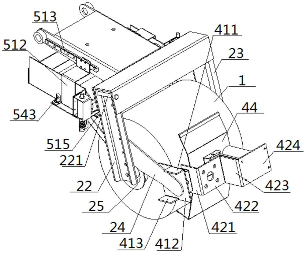
[0066] The outer gripper 41 includes an upper gripping plate 411, a middle gripping plate 412 and a lower gripping plate 413, the inner end of the upper gripping plate 411 is vertically connected with the top of the middle gripping plate 412, and the inner end of the lower gripping plate 413 is connected with the middle gripping plate 413. The bottom end of gripping plate 412 is vertically connected, and the outer ends of upper gripping plate 411 and lower gripping plate 413 all extend toward the direction away from lower yarn base plate 42, and the central axis connecting line between upper gripping plate 411 and lower gripping plate 413 is The projection on the middle grip plate 412 is an oblique line. The lower yarn base plate 42 is a stepped structure, including a vertical plate 421, a flat second plate 422, a vertical third plate 423, and a flat fourth plate 424. Connection, the outer end of the first...

Embodiment 3

[0068] Basic content is the same as embodiment 1, the difference is:

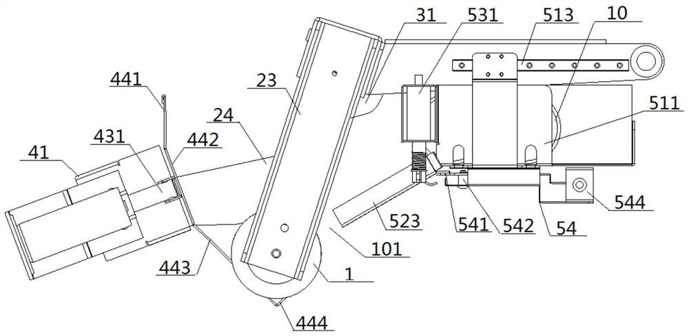
[0069] The concave push plate 44 includes a slanted upper extension plate 441, a vertical middle straight plate 442, an oblique lower extension plate 443 and an upper hook horizontal plate 444. The back side of the vertical middle straight plate 442 is connected with the outer end of the telescopic push rod 431. The top of the middle straight plate 442 is connected with the low end of the inclined upper extension plate 441, the bottom of the vertical middle straight plate 442 is connected with the high end of the inclined lower extension plate 443, and the lower end of the inclined lower extension plate 443 is connected with the bottom of the upper hook horizontal plate 444. Connected, the top of the upper hook horizontal plate 444 is upturned and extended; the inclined upper extension plate 441, the vertical middle straight plate 442, the inclined lower extension plate 443, and the upper hook horizontal pla...


PUM


Abstract

The invention discloses a yarn discharging and tube replacing integrated device. The device comprises a yarn discharging unit, an empty tube storage unit, a winding bobbin clamp and a bobbin clamp connecting plate; the winding bobbin clamp comprises a clamp top cross beam, a movable side arm and a fixed side arm; the rear end of the clamp top cross beam is connected with the front end of the bobbin clamp connecting plate; the yarn discharging unit comprises an outer gripper, a yarn discharging base plate, a driving machine and an inwards-concave push plate; the empty tube storage unit comprises a tube placing part and a tube guiding part; the tube placing part is connected with the bobbin clamp connecting plate; at least one empty tube is arranged in the tube placing part; the front end of the tube placing part is connected with the high end of the tube guiding part; the bottom end of the pipe guiding part extends towards a push plate clamping groove in the yarn discharging unit; and a yarn roll discharging gap is formed between the bottom end of the tube guiding part and the push plate clamping groove. By means of the design, the operation steps can be simplified, automatic yarn discharging and tube replacing are achieved, the operation is smooth, the production efficiency is relatively high, and the production cost can be reduced.

Description

technical field [0001] The invention relates to a technology for replacing yarn rolls in a direct twisting machine, belongs to the field of textile machinery, and in particular relates to an integrated device for changing tubes of lower yarns. Background technique [0002] In the direct twisting machine or doubling machine, when the empty winding bobbin (that is, the empty tube) is wound up on the machine, it becomes a yarn roll. At this time, the yarn roll needs to be removed and replaced with an empty tube. , the operation of removing the yarn roll and replacing the empty tube is mostly manual operation. During the operation, it is necessary to manually raise the bobbin clamp together with the yarn roll, and then remove the yarn roll with the cooperation of both hands, and then lift the yarn roll Place it on the doffing car, and then replace the empty tube on the bobbin clamp with both hands. Not only the steps are cumbersome, but also the labor intensity is relatively hig...

Claims


Application Information

Patent Timeline
IPC IPC(8): D01H9/02
CPCD01H9/02
Inventor 徐巧杨涛梅顺齐陈振姬巧玲祖耀孟凡贺
Owner WUHAN TEXTILE UNIV
Why Eureka
Try Eureka