

Assembly type plastic rod end knuckle bearing and manufacturing method thereof
A technology of plastic rods and end joints, which is applied in the direction of connecting rod bearings, bearing components, shafts and bearings, etc., can solve the problems of high manufacturing cost, low production efficiency, and large plasticity of plastics, so as to improve the smoothness of operation and compact assembly Sex, reduce the effect of front and rear clearance
- Summary
- Abstract
- Description
- Claims
- Application Information
AI Technical Summary
Problems solved by technology
Method used
Image

Examples
Embodiment 1
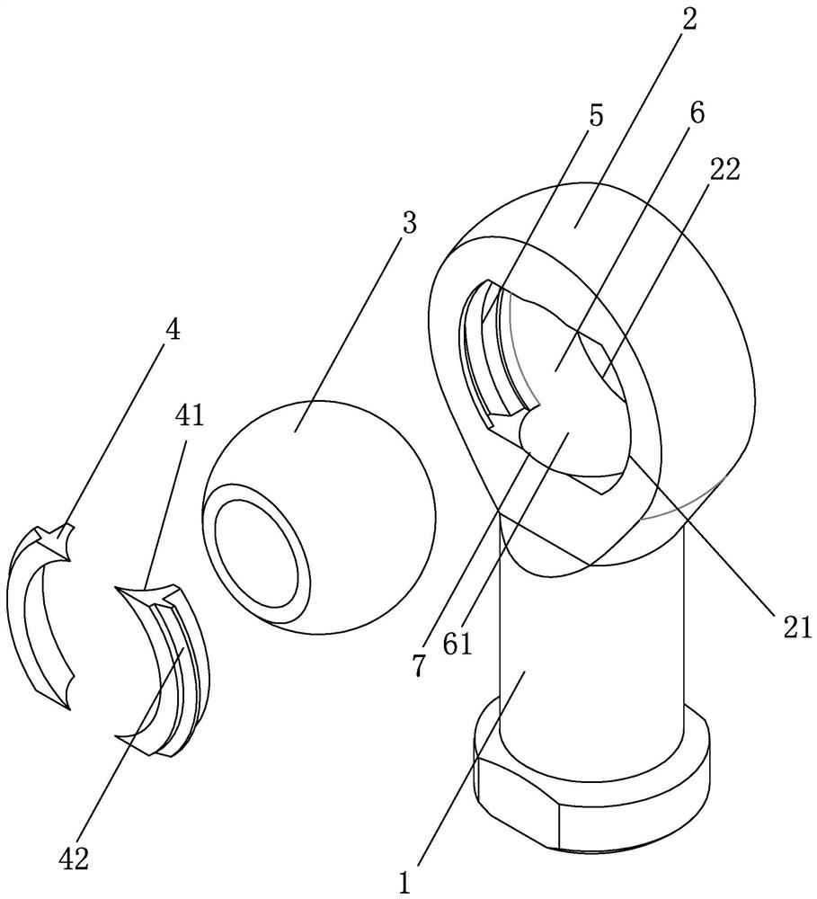
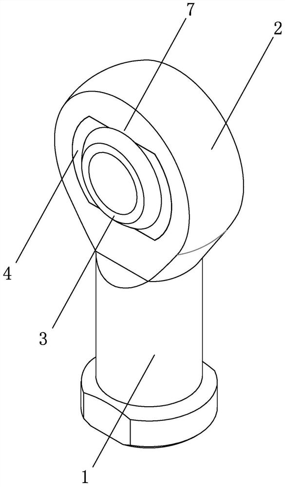
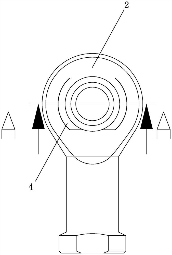
[0033] Such as figure 1 , shown in 2, an assembled plastic rod end joint bearing, including a rod end body 1, an outer ring body 2 is arranged on the rod end body 1, and an inner ring body 3 is arranged in the outer ring body 2; wherein , the outer ring body 2 includes a first ring opening 21 and a second ring opening 22 along the loading direction of the inner ring body 3, and an assembly groove 5 is provided inside the first ring opening 21; wherein, the assembly groove 5 The inner fastening is provided with a sealing member 4 . The assembly groove 5 is used for the inner ring body 3 to be smoothly loaded into the outer ring body 2. After the inner ring body 3 is installed, the sealing member 4 is fastened and connected to the assembly groove 5, and the sealing member 4 can close the first ring opening 21 , in order to prevent dust and other debris from entering between the outer ring body 2 and the inner ring body 3, at the same time limit the front and rear positions of t...
Embodiment 2
[0053]The difference from Embodiment 1 is that in this embodiment, the outer surface of the rod end body 1 away from the outer ring body 2 is provided with an external thread structure, and the rod end body 1 is a screw structure, and this kind of rod end body 1 is used to connect each Screw holes for mechanical equipment.
[0054] The rod end body 1 in embodiment 1 is a female type rod end body 1, and the diversity of the male type rod end body 1 in embodiment 2 can ensure that the rod end joint bearing can adapt to the needs of various mechanical equipment and effectively lift the rod end body. The adaptability and versatility of end joint bearings.
PUM
 Abstract
Description
Claims
Application Information