

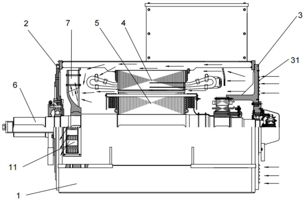
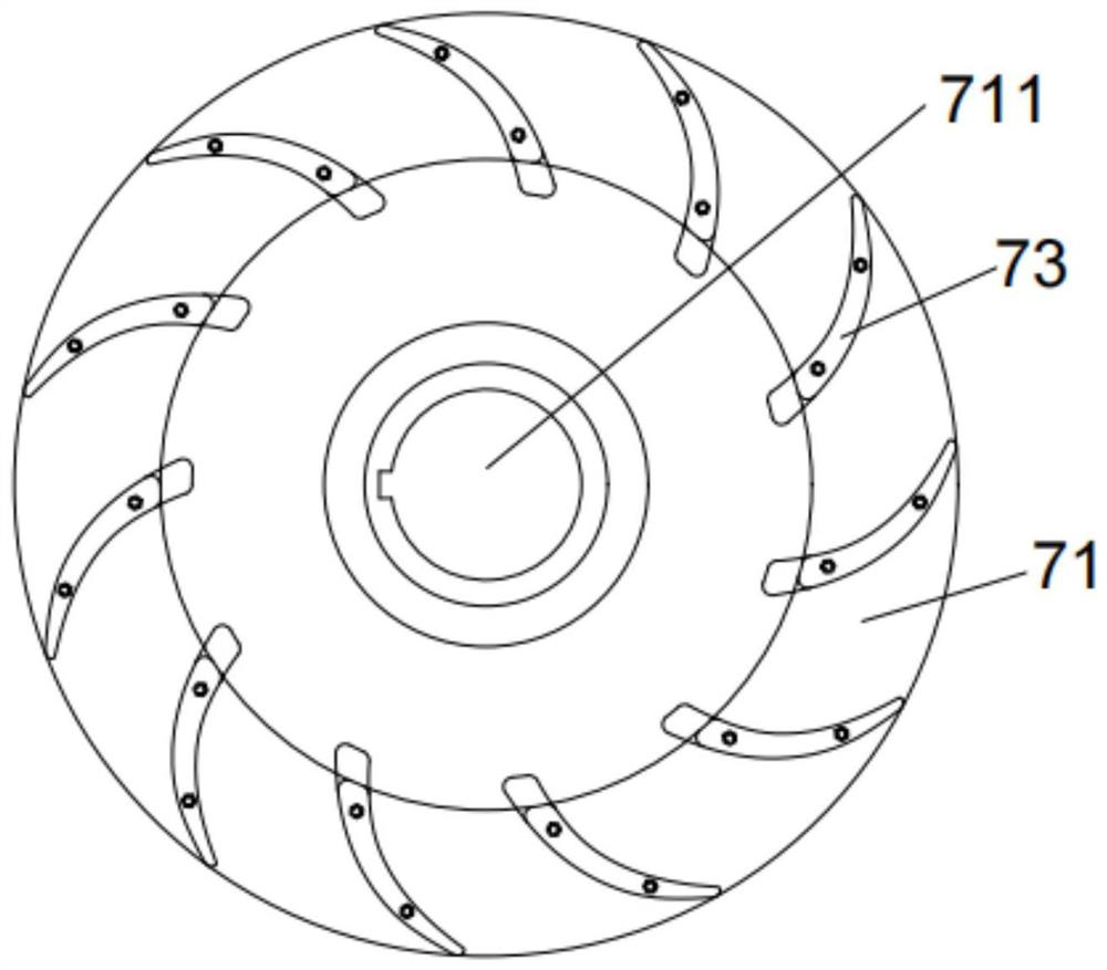
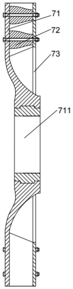
Generator with assembled centrifugal fan
A technology for centrifugal fans and generators, applied in the direction of machines/engines, liquid fuel engines, and components of pumping devices for elastic fluids, etc., can solve the heat dissipation effect, noise, efficiency deviation, can not meet the needs of generators Increase the manufacturing cost and other issues to achieve the effect of convenient and simple connection, low cost and excellent efficiency
- Summary
- Abstract
- Description
- Claims
- Application Information
AI Technical Summary
Problems solved by technology
Method used
Image

Examples
Embodiment Construction
[0039] In the description of the present invention, it should be noted that the terms "center", "upper", "lower", "left", "right", "vertical", "horizontal", "inner", "outer" etc. The indicated orientation or positional relationship is based on the orientation or positional relationship shown in the drawings, and is only for the convenience of describing the present invention and simplifying the description, rather than indicating or implying that the referred device or element must have a specific orientation, or in a specific orientation. construction and operation, therefore, should not be construed as limiting the invention. In addition, the terms "first", "second", and "third" are used for descriptive purposes only, and should not be construed as indicating or implying relative importance.
[0040] In the description of the present invention, it should be noted that unless otherwise specified and limited, the terms "installation", "connection" and "connection" should be un...
PUM
 Abstract
Description
Claims
Application Information