Drawing binding device with deviation rectifying structure for industrial design

An industrial design and drawing technology, applied in book binding, bookbinding, book binding and flattening machine, etc., can solve problems such as the inability to ensure the neatness of the binding, the inability to guarantee the quality of the binding, and the inconvenience to ensure the stability of the drawings, etc. Guaranteed stable placement, fast and efficient binding, and stable effects

Pending Publication Date: 2021-08-06
ANHUI XINHUA UNIV
View PDF0 Cites 1 Cited by
  • Summary
  • Abstract
  • Description
  • Claims
  • Application Information

AI Technical Summary

Problems solved by technology

[0008] The purpose of the present invention is to provide a kind of drawing binding device for industrial design with deviation correcting structure, to solve the problem that the current drawing binding device for industrial design proposed in the above-mentioned background technology mostly adopts manpower to manually use a stapler when binding drawings. Carrying out the binding and fixing of drawings, when it is in use, not only can not guarantee the neatness of binding, but also can not guarantee the quality of binding; although some binding machines for binding have been proposed, there is still a lack of a small, automatic operation The binding machine carries out the binding work of the drawings to ensure the automatic neatness and fixed use of the drawings; when some binding machines are used, it is not convenient to ensure the stability of the drawings, it cannot avoid the deviation of the drawings during the binding, and it is not convenient to carry out The problem of self-regulation

Method used


Image

  • Drawing binding device with deviation rectifying structure for industrial design
  • Drawing binding device with deviation rectifying structure for industrial design
  • Drawing binding device with deviation rectifying structure for industrial design

Examples


Embodiment Construction

[0051] The technical solutions in the embodiments of the present invention will be clearly and completely described below with reference to the accompanying drawings in the embodiments of the present invention. Obviously, the described embodiments are only a part of the embodiments of the present invention, but not all of the embodiments. Based on the embodiments of the present invention, all other embodiments obtained by those of ordinary skill in the art without creative efforts shall fall within the protection scope of the present invention.

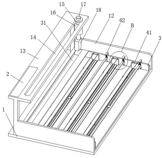
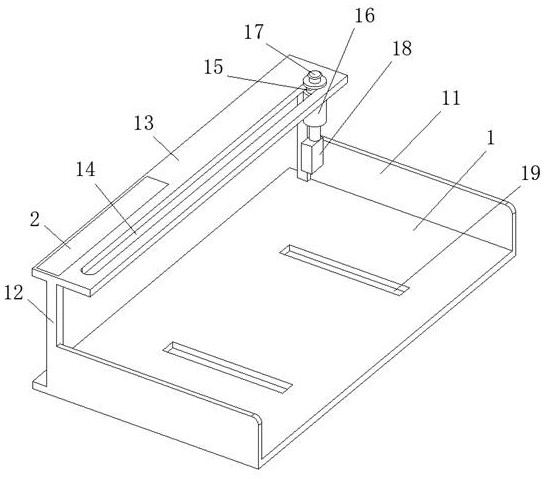
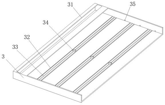
[0052] see Figure 1-16 , the present invention provides a technical solution: a drawing binding device for industrial design with a deviation correction structure, comprising a mounting bottom plate 1, a protective side plate 11, a mounting strut 12, a top plate 13, a chute 14, a slider 15, a telescopic rod 16. Start button 17, binding machine 18, recessed slot 19, controller 2, drawing placement frame 3, binding slot 31, installatio...


PUM


Abstract

The invention discloses a drawing binding device with a deviation rectifying structure for industrial design. The device comprises a frame bottom plate, a controller and a drawing placement frame, the bottom of the frame bottom plate is directly arranged on a table top for use, a top plate is fixed to the top of the upper portion of the frame bottom plate, a sliding block is slidably connected to the front side of the top plate, and a telescopic rod is installed below the sliding block. The bottom end of the telescopic rod is connected with a binding machine, and the top end of the telescopic rod is electrically connected with a starting button. The controller is fixedly embedded into the side of the top plate. The drawing placement frame is rotatably mounted on the top surface of the frame bottom plate, and the drawing placement frame is of a frame structure. According to the drawing binding device, automatic arrangement and alignment of drawings can be guaranteed, stable placement of the drawings is guaranteed, the drawings are conveniently pressed, the binding stability is guaranteed, and rapid and efficient binding use is conveniently guaranteed.

Description

technical field [0001] The present invention relates to the technical field of industrial design, and further relates to the technical field of binding of drawings in industrial design, in particular to a drawing binding device for industrial design with a deviation correction structure. Background technique [0002] The binding machine is a kind of binding machine commonly used in the binding of drawings. It combines and binds multiple sheets of paper, plastic, leather, etc. during work. Design work requires a large number of drawings to describe the structure of the product. In order to facilitate reading and viewing, it is necessary to use a binding device to bind the drawings; [0003] However, in the background of the prior art, there are still some inconveniences when transferring drawings, such as; [0004] 1. At present, when binding drawings, most of them manually use a stapler to bind and fix drawings. When they are used, not only the neatness of the binding, but ...

Claims


Application Information

Patent Timeline
Patent Type & Authority Applications(China)
IPC IPC(8): B42B5/00B42C13/00
CPCB42B5/00B42C13/00
Inventor 赵群牛山林田园
Owner ANHUI XINHUA UNIV
Why Eureka
Try Eureka