Lifeboat with anti-roll function

A technology for anti-rolling and lifeboats, applied in the field of lifeboats, can solve problems such as inconvenient rescue methods, violent shaking of lifeboats, and secondary injuries of those who fall into the water.

Pending Publication Date: 2021-08-06
何庆清
View PDF0 Cites 0 Cited by
  • Summary
  • Abstract
  • Description
  • Claims
  • Application Information

AI Technical Summary

Problems solved by technology

At present, when the rescuers on most lifeboats are salvaging and rescuing the drowning person, the rescuer needs to lift the drowning person upwards and drag the drowning person into the hull from the side of the ship. This process is likely to cause secondary damage to the drowning person. Injury, the rescue method is also very inconvenient, and when the person in the water is dragged from the edge of the ship into the hull, it is easy to cause excessive gravity on one side and shift the center of gravity. There is a risk of violent shaking or rollover of the rescue boat during the rescue process. Therefore, the present invention In view of the above problems, a lifeboat with anti-rolling function has been invented.

Method used


Image

  • Lifeboat with anti-roll function
  • Lifeboat with anti-roll function
  • Lifeboat with anti-roll function

Examples


Embodiment 1

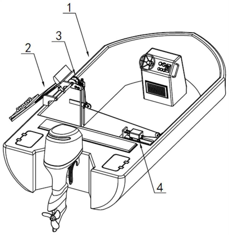
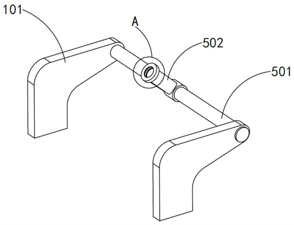
[0033] Such as Figure 1 to Figure 12 As shown, a lifeboat with its own anti-rolling function includes a hull 1, a rotating seat 101 is fixedly arranged on one side of the hull 1, and a turning mechanism 2 is arranged on the rotating seat 101, so that The overturning mechanism 2 is used to carry and support people who fall into the water. One side of the overturning mechanism 2 is fixedly connected with a drive assembly 3. The hull 1 is also fixedly equipped with a counterweight assembly 4. The drive assembly 3 is used to control the overturning mechanism. 2 Turn over to lift the person who falls into the water and drive the counterweight assembly 4 to move horizontally to the other side of the hull 1 relative to the turning mechanism 2 to maintain the overall balance of the hull 1. The turning mechanism 2 is also provided with a rotation component 5, The autorotation assembly 5 is used to rotate the overturning mechanism 2 to cooperate with the rescuers on the hull 1 to lift ...

Embodiment 2

[0043] Such as Figure 11 As shown, the parts that are the same as or corresponding to those in Embodiment 1 adopt the reference numerals corresponding to Embodiment 1. For the sake of simplicity, only the differences between Embodiment 1 and Embodiment 1 are described below; the differences between Embodiment 2 and Embodiment 1 The difference is that: the other end of the turning mechanism 2 is provided with a drawing assembly 7, and the drawing assembly 7 includes a support plate 701 slidably arranged in the through groove 204, and the two sides of the bearing plate 201 are provided with limited The position chute 702, the two sides of the support plate 701 are provided with the limit slide bar 703 matched with the limit chute 702, and the limit slide bar 703 is slidably arranged in the limit chute 702 , the outer end of the support plate 701 is also fixedly provided with a support pillow 704 .

[0044] It should be pointed out that, for the drawing assembly 7 provided in t...


PUM


Abstract

The invention relates to a lifeboat with the anti-roll function. The lifeboat comprises a boat body, wherein a rotating seat is fixedly arranged on a boat edge of one side of the boat body, a turnover mechanism is rotationally arranged on the rotating seat and used for bearing and supporting a drowning person, a driving assembly is fixedly connected to one side of the turnover mechanism, a counterweight assembly is further fixedly arranged on the boat body, the driving assembly is used for controlling the turnover mechanism to turn over to lift a borne person falling into water and driving the counterweight assembly to horizontally move towards the other side, opposite to the turnover mechanism, of the ship body to keep the whole ship body balanced, and the turnover mechanism is further provided with an autorotation assembly; the self-rotation assembly is used for rotating the overturned overturning mechanism so as to cooperate with rescue workers on the ship body to lift out the person falling into water on the overturning mechanism, the self-rotation assembly is arranged to rotate so as to cooperate with the rescue workers to rescue the person falling into water on the overturning mechanism, and the overturning mechanism is in linkage fit with the counterweight assembly; the overall balance of the ship body during rescue is guaranteed, and the rescue process can be safely and efficiently carried out.

Description

technical field [0001] The invention relates to the technical field of lifesaving equipment, in particular to a lifeboat with a built-in anti-rolling function. Background technique [0002] The lifeboat is the main means of transportation for flood fighting and rescue, and it is also the main tool for material or personnel rescue in floods, waterlogging and other disasters. The easy-to-use rescue tools can greatly save rescue time and ensure the timeliness of flood fighting and disaster relief. At present, when the rescuers on most lifeboats are salvaging and rescuing the drowning person, the rescuer needs to lift the drowning person upwards and drag the drowning person into the hull from the side of the ship. This process is likely to cause secondary damage to the drowning person. Injury, the rescue method is also very inconvenient, and when the person in the water is dragged from the edge of the ship into the hull, it is easy to cause excessive gravity on one side and shif...

Claims


Application Information

Patent Timeline
Patent Type & Authority Applications(China)
IPC IPC(8): B63C9/28B63C9/02B63B43/02
CPCB63B43/02B63C9/02B63C9/28
Inventor 何庆清
Owner 何庆清
Why Eureka
Try Eureka