Automatic temperature control device for mass concrete

A mass concrete, automatic temperature control technology, applied in the field of concrete equipment, can solve the problems of increasing material cost, high use time requirements, changing concrete properties, etc., to achieve the effect of reducing equipment manufacturing costs, construction costs, and stress concentration.

Pending Publication Date: 2021-08-06
POWERCHINA CHENGDU ENG
View PDF0 Cites 0 Cited by
  • Summary
  • Abstract
  • Description
  • Claims
  • Application Information

AI Technical Summary

Problems solved by technology

[0004] Among them, adjusting the concrete ratio can be realized by selecting low-heat-of-hydration cement and improving the aggregate gradation, but it will change the properties of the concrete and increase the material cost; reducing the thickness of the concrete pouring layer and covering the surface with insulation materials is also easy to achieve, but for The impact of construction progress is relatively large; the method of reserving water injection and cooling holes is the most widely used, but it is difficult to control the water temperature through water injection and cooling, and it is difficult to identify the temperature difference of each unit volume of concrete. Inappropriate water temperature adjustment may be counterproductive. Real-time artificial The workload of temperature measurement is large, and it is not suitable to measure the internal temperature of concrete. The process is complicated and the accuracy is not high. The temperature control effect in the concrete structure is not significant; so it is necessary to study the automatic temperature control device of mass concrete

Method used


Image

  • Automatic temperature control device for mass concrete
  • Automatic temperature control device for mass concrete
  • Automatic temperature control device for mass concrete

Examples


Embodiment Construction

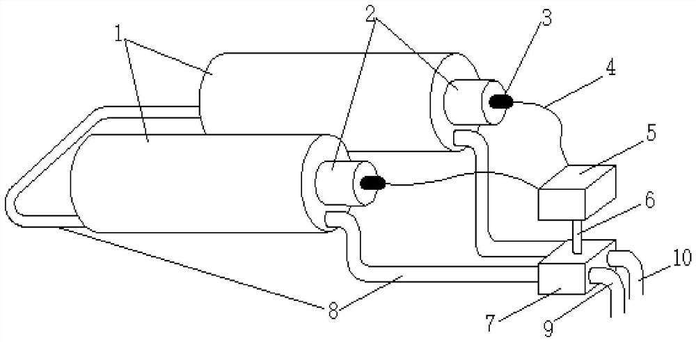
[0020] In order to solve the problem that the concrete cannot be automatically controlled during the concrete pouring and curing process, the embodiment of the present invention provides an automatic temperature control device suitable for large-volume concrete, which consists of a water cooling system main body, a temperature control system, and a transmission structure. Partial composition.

[0021] The main body of the water cooling system includes a pressure-resistant steel pipe 1, a PVC riser 2 and a temperature sensing element 3 arranged inside the pressure-resistant steel pipe 1; a closed medium chamber is formed between the pressure-resistant steel pipe 1 and the PVC riser 2, and the medium chamber is water-cooled. medium (temperature control medium), the temperature sensing element 3 is inside the PVC water riser 2 . Among them, the pressure-resistant steel pipe 1 is used to protect the PVC water riser 2 from being crushed by concrete gravity and concrete expansion de...


PUM


Abstract

The invention relates to the field of concrete equipment, and discloses an automatic temperature control device for mass concrete so as to automatically control the temperature of the concrete in the concrete pouring and curing process. The automatic temperature control device comprises a liquid cooling system main body, a temperature control system, and a data transmission structure and a medium transmission structure which connect the liquid cooling system main body and the temperature control system; the liquid cooling system main body comprises a pressure-resistant pipe, a liquid isolation pipe and a temperature sensing element, wherein the temperature sensing element is arranged in the liquid isolation pipe, the liquid isolation pipe is arranged in the pressure-resistant pipe, and a closed medium cavity is formed between the pressure-resistant pipe and the liquid isolation pipe; and the temperature control system comprises a temperature monitoring system, a hydraulic control system and a braking system contained between the temperature monitoring system and the hydraulic control system, wherein the temperature monitoring system is in data communication with the temperature sensing element through the data transmission structure, and the hydraulic control system is in temperature control medium circulation with the medium cavity through the medium transmission structure. The automatic temperature control device is suitable for concrete pouring and curing.

Description

technical field [0001] The invention relates to the field of concrete equipment, in particular to an automatic temperature control device for large-volume concrete. Background technique [0002] During the pouring and curing process of concrete, a large amount of heat of hydration will be emitted, and the process of heating and cooling in different locations will be completed in a long period of time, resulting in uneven expansion and contraction of the concrete volume, which will cause concrete cracks. It is the most prominent in the mass concrete structure, so it is very important to monitor and control the temperature of the concrete, which can effectively reduce the cracks caused by the uneven temperature of the concrete. [0003] Existing methods for controlling concrete temperature cracks are mainly achieved by adjusting the ratio of concrete to soil, reducing the thickness of the concrete pouring layer, reserving holes for water injection and cooling, sprinkling water...

Claims


Application Information

Patent Timeline
Patent Type & Authority Applications(China)
IPC IPC(8): C04B40/00C04B40/02
CPCC04B40/0075C04B40/02
Inventor 吴启凡代磊席景华杨洲余琳
Owner POWERCHINA CHENGDU ENG
Why Eureka
Try Eureka