Spinning machine drafting zone cleaning mechanism and cleaning method

A technology for cleaning mechanisms and spinning machines, applied to cleaning methods and appliances, cleaning methods using gas flow, chemical instruments and methods, etc., which can solve the problems of short effective blowing distance, low cleaning accuracy, and increased yarn defects , to achieve the effect of high utilization of blowing range, ideal cleaning effect and high cleaning accuracy

Active Publication Date: 2021-08-10
XINCHANG AOTAI MACHINERY MFG
View PDF7 Cites 1 Cited by
  • Summary
  • Abstract
  • Description
  • Claims
  • Application Information

AI Technical Summary

Problems solved by technology

[0004] However, the number and position design of the blowing outlets on the current cleaning equipment are unreasonable. At present, only the spinning machine can be blown at a relatively long distance, and the blowing range of one blowing outlet is relatively large, so it is impossible to easily accumulate air. Targeted cleaning of the lint area, resulting in low cleaning accuracy, short effective blowing distance, and unsatisfactory cleaning effect
[0005] On the one hand, the reason is that the normal weaving work of the normal yarn will be affected when the distance is too short or the wind is strong; especially in the drafting area of ​​the spinning machine, the top roller bearings in this area are very easy to form waste cotton lint, but this The yarn in the area will be very fragile due to being suspended on the top roller bearing, which will cause the wind force that is too small to effectively remove the waste cotton accumulation, but the wind force that can satisfy the removal of waste cotton accumulation will easily cause the yarn in this area to be damaged. Breakage or increase in yarn defects, so that a balanced state with a good cleaning effect cannot be achieved in this area

Method used


Image

  • Spinning machine drafting zone cleaning mechanism and cleaning method
  • Spinning machine drafting zone cleaning mechanism and cleaning method
  • Spinning machine drafting zone cleaning mechanism and cleaning method

Examples


Embodiment

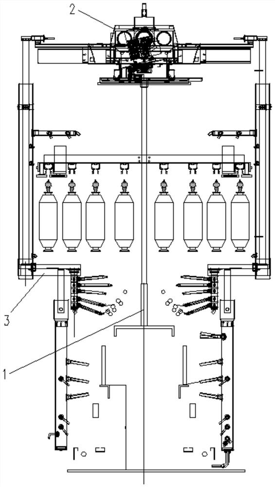
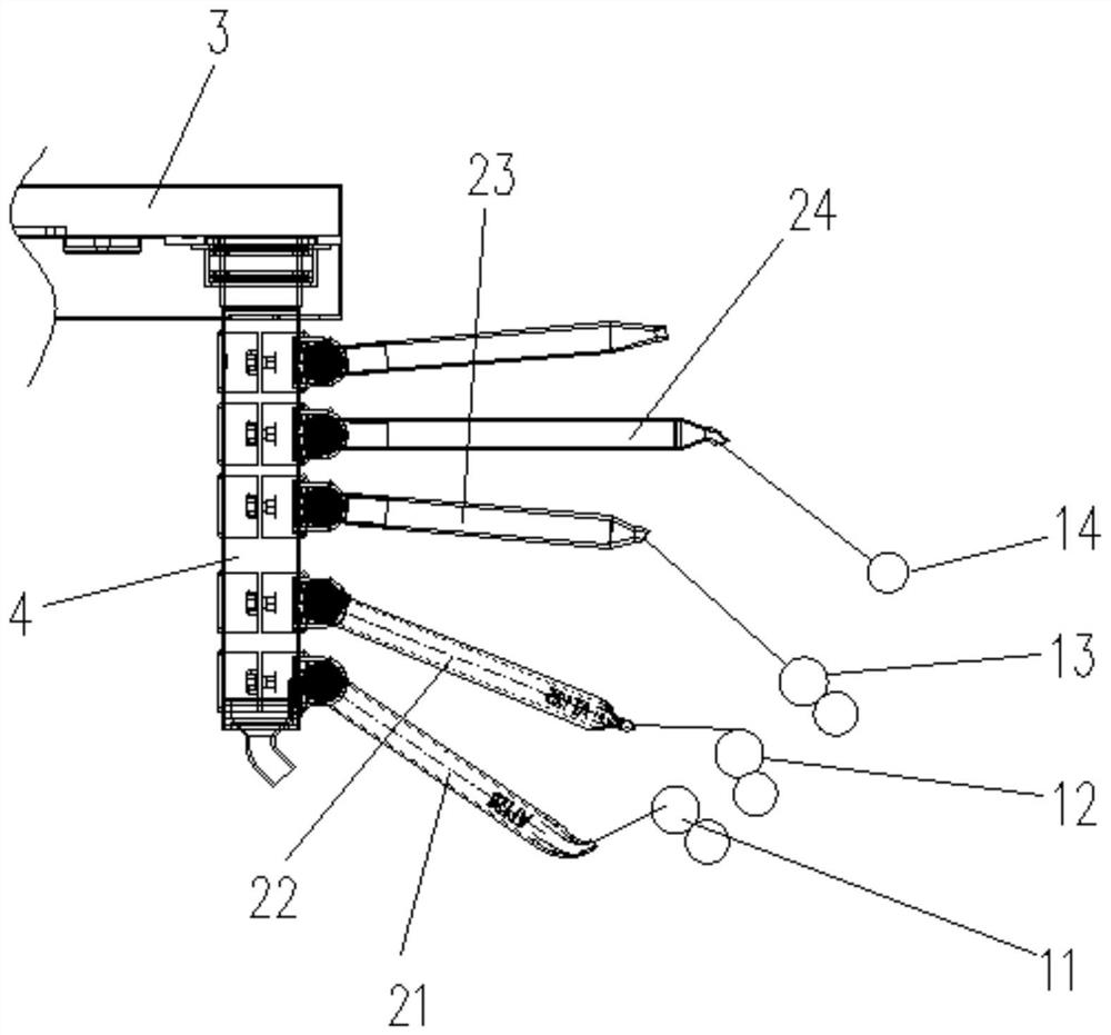
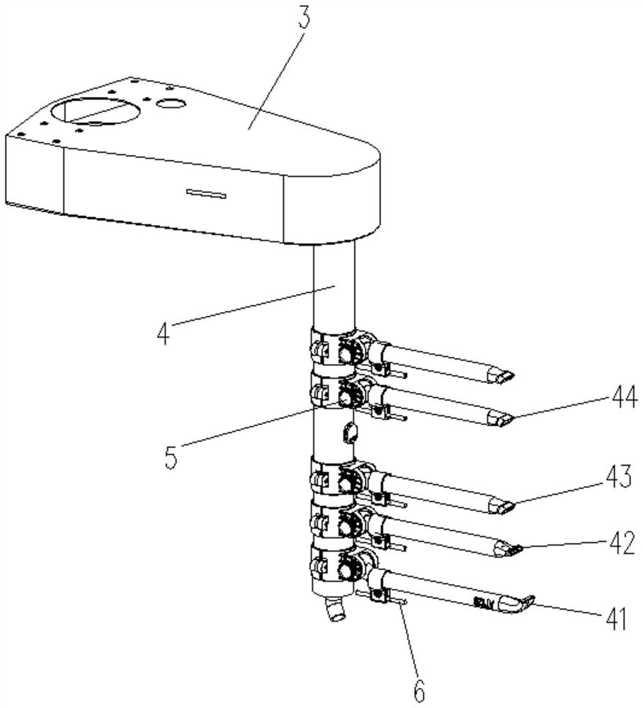
[0027] Embodiment: a kind of drafting area cleaning mechanism of spinning machine, such as Figure 1-4 As shown, the working areas on both sides of the spinning machine 1 are respectively provided with a first top roller bearing 11, a second top roller bearing 12, a third top roller bearing 13 and a fourth top roller bearing 14, which are relatively inclined from bottom to top, The area between the first top roller bearing 11 and the second top roller bearing 12 is a draft zone, and waste cotton is easily accumulated on the first top roller bearing 11 and the second top roller bearing 12 on both sides of this area, wherein It is even worse with the first top roller bearing 11, but the yarn in this region is easy to cause broken yarn or yarn defect when the blowing wind is strong.

[0028] In view of the above situation, the cleaning mechanism of this embodiment is provided with blowing components on both sides of the spinning machine 1 respectively. Since the blowing component...


PUM


Abstract

The invention discloses a spinning machine drafting zone cleaning mechanism and a cleaning method. The spinning machine drafting zone cleaning mechanism comprises a main machine, the main machine is provided with a blowing main pipe extending to the side face of a spinning machine, the blowing main pipe is connected with a relatively vertical blowing branch pipe, and the blowing branch pipe is provided with at least four blowing pipes; the at least four blowing pipes are a first blowing pipe, a second blowing pipe, a third blowing pipe and a fourth blowing pipe in sequence from bottom to top, and blowing openings of the first blowing pipe and the second blowing pipe are flat openings; the blowing opening of the first blowing pipe is bent upwards, an included angle between the air outlet direction of the blowing opening of the first blowing pipe and a pipe body of the first blowing pipe is 45-135 degrees, and a blowing point of the first blowing pipe is located in a quarter area of the outer side of a first leather roller bearing; and the included angle between the air outlet direction of the blowing opening of the second blowing pipe and a pipe body of the second blowing pipe is 110-180 degrees, and the blowing point of the second blowing pipe is located on the right side of the top of a second leather roller bearing. The cleaning precision is high, the blowing range utilization degree is high, the cleaning effect is relatively ideal, and the situation that yarn breaking or yarn faults occur in a drafting zone is effectively reduced.

Description

technical field [0001] The invention relates to the technical field of spinning machine cleaning, in particular to a cleaning mechanism and a cleaning method for a drafting area of ​​a spinning machine. Background technique [0002] The textile cleaning machine is a kind of cleaning equipment used on textile equipment to blow and suck the fibers that are interrupted during the yarn processing process, as well as the flying flowers floating in the air and the lint that falls on the textile equipment. It is mainly used to clean up and around the spinning machine. Cotton waste in the area. [0003] Take the existing spinning frame, roving frame or self-winding machine as an example. These types of spinning machines are generally installed together on a production line, which also provides convenience for the design and assembly of their cleaning equipment. In the prior art, there are cleaning mechanisms for these types. Generally, a guide rail is set along the length of the pr...

Claims


Application Information

Patent Timeline
Patent Type & Authority Applications(China)
IPC IPC(8): B08B5/02
CPCB08B5/02Y02W30/66
Inventor 赵小敏任斌峰
Owner XINCHANG AOTAI MACHINERY MFG
Why Eureka
Try Eureka