Filter module, and method for determining the state of a filter element

A filter and element technology, applied in the field of filter modules, can solve the problems of measurement system failure, excessive energy, consumption, etc.

Pending Publication Date: 2021-08-13
CARL FREUDENBERG KG
View PDF5 Cites 0 Cited by
  • Summary
  • Abstract
  • Description
  • Claims
  • Application Information

AI Technical Summary

Problems solved by technology

If, for example, one filter element is damaged and has gaps, and if another filter element is strongly loaded and can barely pass air, the pressure loss measured over the entire filter module provides an unaffected value, which cannot be extrapolated the true state of a single filter element
[0004] A disadvantage of the overall measurement of the pressure loss is that some filter elements cannot be cleaned or replaced at the ideal point in time, since their individual status is unknown
Therefore, mo

Method used


Image

  • Filter module, and method for determining the state of a filter element
  • Filter module, and method for determining the state of a filter element
  • Filter module, and method for determining the state of a filter element

Examples


Embodiment Construction

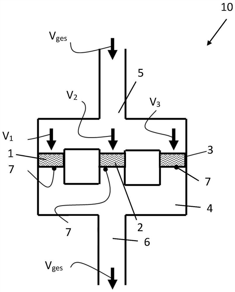
[0052] figure 1 The structure of the filter module 10 according to the invention is shown. In the air channel 4 of the filter module 10 there is a plurality of filter elements, here a first filter element 1 , a second filter element 2 and a third filter element 3 arranged in parallel connection. However, a greater number of filter elements arranged in a matrix is ​​also conceivable. The air flows from the raw gas side 5 to the clean gas side 6 and is filtered there. A total volume flow V flows at the inlet and outlet of the filter module 10 ges . The total volume flow V ges This splits so that the first sub-volume flow V 1 Flowing through the first filter element 1, the second subvolume flow V 2 flows through the second filter element 2 and the third sub-volume flow V 3 flows through the third filter element V 3 . In order to be able to make statements about the state of the respective filter element 1 , 2 , 3 , a sensor 7 is arranged on each filter element 1 , 2 , 3 ...


PUM


Abstract

The invention relates to a filter module (10) for filtering a fluid flow, having a plurality of filter elements (1, 2, 3) such as filter cartridges (8) arranged in parallel with one another in a fluid channel (4). A sensor (7), namely a flow sensor, is attached to each filter element (1, 2, 3) for the purpose of determining the state, in particular state of loading, of the respective filter element (1, 2, 3). The invention furthermore relates to a method for determining the state of a filter element. The configuration according to the invention advantageously makes it possible to determine the state of individual filter elements of a filter module and thus to intervene when an individual filter element is not fully functional.

Description

technical field [0001] The invention relates to a filter module for filtering a fluid flow, having a plurality of filter elements arranged parallel to one another in a fluid channel, wherein a sensor is attached to each filter element. The invention also relates to a method for determining the state of a filter element. Background technique [0002] In installations requiring clean air, it is standard to arrange several filter elements parallel to one another in order to be able to provide a large quantity of clean air. Such a filter module with a plurality of filter inserts is shown, for example, in US 7 294 163 B1. [0003] In order to monitor the state of the filter module, the static pressure difference, ie the pressure loss, is usually measured across the filter module. However, this general consideration is rarely useful for being able to make statements about the state of the individual filter elements since the different filter elements of the filter module do not ...

Claims


Application Information

Patent Timeline
IPC IPC(8): B01D46/00B01D46/44B01D46/52
CPCB01D46/0086B01D46/444B01D46/525B01D46/58B01D46/521B01D46/446B01D46/12B01D46/2411B01D2267/30
Inventor S·克卢克R·塔珀
Owner CARL FREUDENBERG KG
Why Eureka
Try Eureka