Laser joint cutting device with adjustable machining size and controllable taper

A size processing and laser cutting technology, which is applied in metal processing equipment, laser welding equipment, manufacturing tools, etc., can solve the problems of difficult integration, high cost, and complex processing, and achieve the effect of convenient operation, simple structure, and easy adjustment

Inactive Publication Date: 2021-08-13
EAST CHINA NORMAL UNIV
View PDF7 Cites 2 Cited by
  • Summary
  • Abstract
  • Description
  • Claims
  • Application Information

AI Technical Summary

Problems solved by technology

[0004] The purpose of the present invention is to overcome the existing technical limitations and provide a laser cutting device with controllable taper and adjustable slit width, which is used to solve the problems of high cost, difficult integration and complicated processing existing in current laser processing

Method used


Image

  • Laser joint cutting device with adjustable machining size and controllable taper
  • Laser joint cutting device with adjustable machining size and controllable taper
  • Laser joint cutting device with adjustable machining size and controllable taper

Examples


Embodiment 1

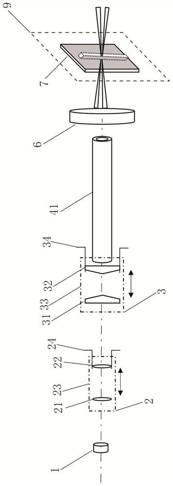
[0046] refer to figure 1 , using the structure of the quarter wave plate 1 of the present invention, the divergence angle regulator 2, the axicon lens pair 3, the focusing lens 6 and the workbench 9 to cut a rectangular groove on the workpiece 7;

[0047] The laser wavelength range of the selected laser is 100nm-12um; the pulse width range is 50fs-100ms;

[0048] The first step: install the workpiece 7 on the workbench 9;

[0049] The second step: adjust the divergence angle adjuster 2 according to the width of the workpiece 7 to be cut;

[0050] Step 3: Adjust the axicon lens pair 3 to the initial position, and the laser focal point passes through the focusing lens 6 in turn according to the set path, and acts on the upper surface of the workpiece 7 on the workbench 9;

[0051] Step 4: adjust the divergence angle regulator adjusting ring 24 of the divergence angle regulator 2, and adjust the divergence angle by changing the position of the concave lens 21 and the convex len...

Embodiment 2

[0054] refer to figure 1 , adopt the structure of the quarter-wave plate 1 of the present invention, the divergence angle regulator 2, the axicon lens pair 3, the focusing lens 6 and the workbench 9 to cut a tapered groove on the workpiece 7;

[0055] The laser wavelength range of the selected laser is 100nm-12um; the pulse width range is 50fs-100ms;

[0056] The first step: the workpiece 7 is installed on the workbench 9;

[0057] The second step: adjust the divergence angle adjuster 2 according to the width of the workpiece 7 to be cut;

[0058] Step 3: Adjust the axicon lens pair 3 to the initial position, and the laser focal point passes through the focusing lens 6 in turn according to the set path, and acts on the upper surface of the workpiece 7 on the workbench 9;

[0059] The fourth step: adjust the taper and adjust the axicon pair of 3 axicons to adjust the ring 34, by controlling the distance between the first axicon 31 and the second axicon 32, to control the proc...

Embodiment 3

[0062] refer to Figure 6 , adopt the structure of quarter-wave plate 1 of the present invention, divergence angle regulator 2, axicon lens pair 3, mirror 4, focusing lens 6 and workbench 9 to cut tapered groove on workpiece 7;

[0063] Since the reflector 4 is set in the optical path, the laser beam is reflected from horizontal to vertical, and the laser wavelength range of the selected laser is 100nm-12um; the pulse width range is 50fs-100ms;

[0064] The first step: install the workpiece 7 on the workbench 9;

[0065] The second step: adjust the divergence angle adjuster 2 according to the width of the workpiece 7 to be cut;

[0066] Step 3: Adjust the axicon lens pair 3 to the initial position, and the laser focal point passes through the focusing lens 6 in turn according to the set path, and acts on the upper surface of the workpiece 7 on the workbench 9;

[0067] Step 4: adjust the divergence angle regulator adjusting ring 24 of the divergence angle regulator 2, and ad...


PUM


Abstract

The invention discloses a laser joint cutting device with an adjustable machining size and a controllable taper. The device is composed of a quarter-wave plate, a divergence angle adjuster, a conical lens pair (additionally provided with a reflecting mirror or a scanning galvanometer), a focusing lens and a workbench. According to the device, the purpose of seam width control is achieved by adjusting the divergence angle state of the divergence angle adjuster; the purpose of processing a zero cone seam or an inverted cone seam is achieved by adjusting the focusing state of the cone lens pair to control the laser beam; by means of swinging of the scanning galvanometer or movement of the servo motor, laser cutting is expanded to laser engraving, and the device facilitates the laser machining of workpieces with complex patterns; and the device has the advantages of being simple in structure, easy to adjust, convenient to operate, convenient to integrate with conventional equipment and low in equipment cost.

Description

technical field [0001] The invention relates to the technical field of laser cutting, in particular to a laser cutting device with adjustable processing size and controllable taper. Background technique [0002] Laser cutting is that the high-energy-density laser focus generated by the laser beam passing through the focusing system acts on the surface of the workpiece, so that the material at the position of the laser focus is rapidly melted, vaporized, and ablated, thereby achieving the cutting effect, and Gaussian beam cutting usually due to its beam characteristics And the mechanism of laser-matter interaction is prone to the problem of cutting taper. [0003] In the prior art, the cutting method to achieve controllable taper is to deflect the beam at different angles by the rotary cutting head, and then cooperate with the movement of the processing platform to achieve it. However, the cost of the rotary cutting head used in this method is high, and at the same time, the ...

Claims


Application Information

Patent Timeline
Patent Type & Authority Applications(China)
IPC IPC(8): B23K26/046B23K26/06B23K26/064B23K26/38
CPCB23K26/046B23K26/064B23K26/0648B23K26/0643B23K26/38
Inventor 陈蔚程亚李晓龙储蔚齐家
Owner EAST CHINA NORMAL UNIV
Why Eureka
Try Eureka