Fabricated type building module pouring device

A prefabricated and architectural technology, which is applied in the direction of supply devices, ceramic molding workshops, ceramic molding machines, etc., can solve the problems of uneven concrete, uneven strength of prefabricated modules, and high labor intensity, and achieve the effect of uniform and fine concrete

Active Publication Date: 2021-08-13
CHONGQING VOCATIONAL INST OF ENG
View PDF13 Cites 2 Cited by
  • Summary
  • Abstract
  • Description
  • Claims
  • Application Information

AI Technical Summary

Problems solved by technology

[0002]Currently, the pouring of concrete prefabricated modules is done manually. big
In addition, in the process of pouring prefabricated modules, concrete needs to be poured into the formwork box. Due to the low fluidity of the concrete, the concrete in the formwork box is often high in the middle and low on both sides, resulting in The concrete is uneven, resulting in uneven strength of the prefabricated modules, resulting in the quality of the prefabricated modules not meeting the requirements

Method used


Image

  • Fabricated type building module pouring device
  • Fabricated type building module pouring device
  • Fabricated type building module pouring device

Examples


Embodiment 1

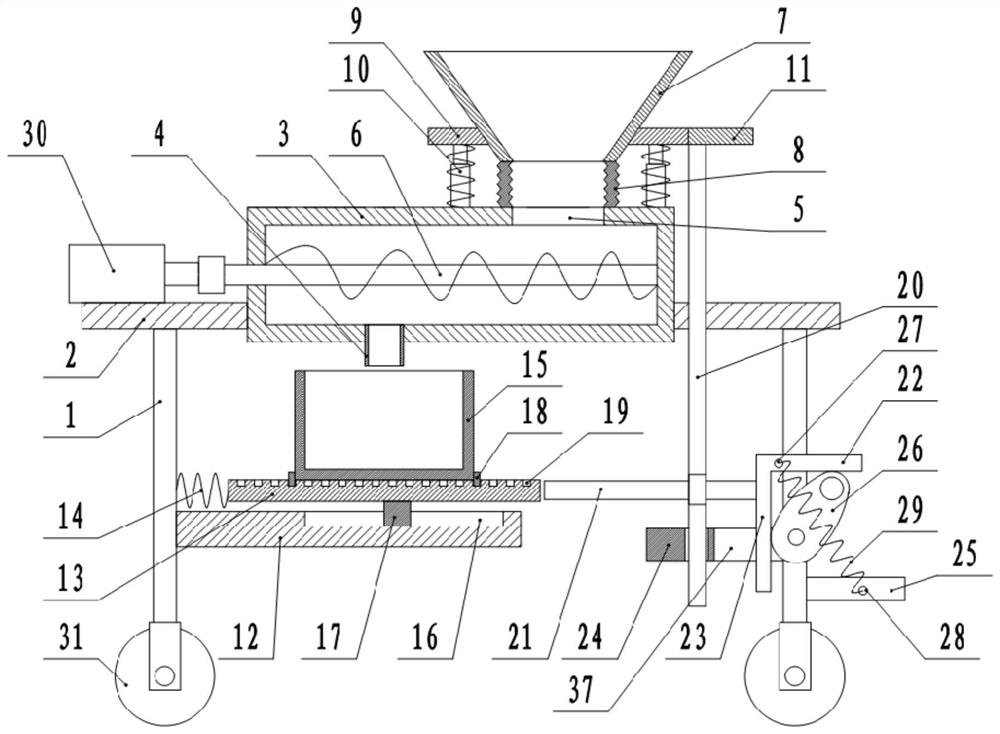
[0029] The embodiment is basically as attached figure 1 Shown: an assembly type building module pouring device, including a frame 1, the top of the frame 1 is vertically welded and fixed with a connecting plate 2, and in this embodiment, a traveling wheel 31 is connected to the bottom of the frame 1.

[0030] Connecting plate 2 is connected with mixing tank 3, and in this embodiment, mixing tank 3 and connecting plate 2 are fixed by bolts, and mixing tank 3 is provided with stirring unit, and mixing unit comprises stirring bar 6 and driving motor 30 in the present embodiment, drives The motor 30 is located on the connecting plate 2 . The stirring rod 6 is welded and fixed with a spirally arranged stirring knife, one end of the stirring rod 6 is rotatably connected with the side wall of the mixing tank 3 through a bearing, and the other end of the stirring rod 6 extends out of the mixing tank 3 and is connected to the drive motor 30 through a shaft coupling fixed.

[0031] Th...

Embodiment 2

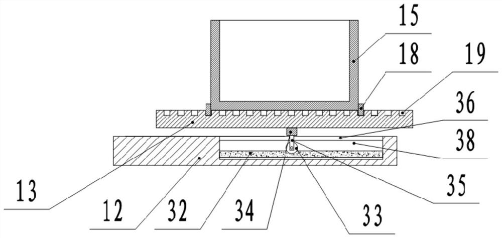
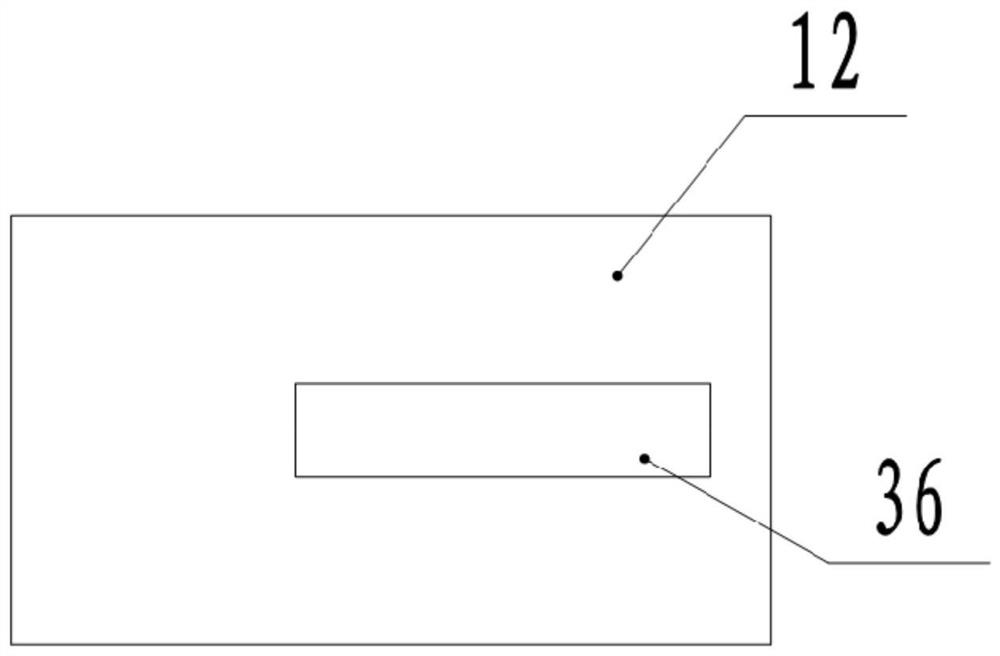
[0047] Such as figure 2 with image 3 As shown, a prefabricated building module pouring device differs from the first embodiment in that the sliding fit structure between the sliding plate 13 and the fixed plate 12 in this solution is different from that in the first embodiment, specifically: in this embodiment A sliding cavity 38 is provided on the fixed plate 12, and a bar-shaped hole 36 communicating with the sliding cavity 38 is opened on the top of the fixed plate 12. The width of the bar-shaped hole 36 is smaller than the width of the sliding cavity 38.

[0048] The bottom end of the sliding plate 13 is welded and fixedly connected with a moving block 34, the width of the moving block 34 is greater than the width of the strip hole 36, and the moving block 34 is positioned above the fixed plate 12, and the bottom end of the moving block 34 is fixedly connected with a support plate 35 by screws. , the bottom end of the support plate 35 extends into the slide chamber 38 a...


PUM


Abstract

The invention relates to the field of fabricated buildings, and discloses a fabricated type building module pouring device. The device comprises a rack, the top end of the rack is connected with a connecting plate, the connecting plate is connected with a stirring barrel, a stirring unit is arranged in the stirring barrel, the stirring barrel is communicated with a feeding hopper and a discharging pipe, and the rack is fixedly connected with a fixed plate. The fixed plate is located below the stirring barrel, a sliding plate is horizontally and slidably arranged on the fixed plate and is matched with the fixed plate, a mold groove box with the open top end is arranged on the sliding plate, the discharging pipe is arranged right opposite to the top of the mold groove box, and an elastic piece is connected between the rack and the sliding plate. A driving unit for intermittently pushing the sliding plate to horizontally slide is arranged on the rack. Concrete in the mold groove box can be uniformly distributed, so that the quality of a prefabricated module is improved.

Description

technical field [0001] The invention relates to the field of prefabricated buildings, in particular to a pouring device for prefabricated building modules. Background technique [0002] At present, the pouring of concrete prefabricated modules is done manually. Before pouring the prefabricated modules, the pouring device needs to be moved to the vicinity of the prefabricated modules. This method is labor-intensive. In addition, in the process of pouring prefabricated modules, concrete needs to be poured into the formwork box. Due to the low fluidity of the concrete, the concrete in the formwork box is often high in the middle and low on both sides, resulting in The concrete is uneven, resulting in uneven strength of the prefabricated modules, resulting in the quality of the prefabricated modules not meeting the requirements. Contents of the invention [0003] The invention intends to provide a pouring device for an assembled building module, which can make the concrete in...

Claims


Application Information

Patent Timeline
Patent Type & Authority Applications(China)
IPC IPC(8): B28B1/087B28B23/02B28B13/02B28B15/00
CPCB28B1/0873B28B23/02B28B13/0235B28B15/002B28B2001/0876Y02W30/91
Inventor 冉云霞成声健
Owner CHONGQING VOCATIONAL INST OF ENG
Why Eureka
Try Eureka