A microneedle patch transfer device

A microneedle patch and microneedle technology, which is applied in the directions of transportation and packaging, thin material handling, and delivery of objects, can solve problems such as low work efficiency, high labor intensity, and the impact of microneedle patch quality, and improve the efficiency of posting , Precise pasting, avoiding the effect of air bubbles

Active Publication Date: 2022-06-03
SHANDONG HOACO AUTOMATION TECH
View PDF0 Cites 0 Cited by
  • Summary
  • Abstract
  • Description
  • Claims
  • Application Information

AI Technical Summary

Problems solved by technology

However, there is still no special transfer equipment for pasting the microneedle patch on the adhesive tape. The paste operation of the microneedle patch on the adhesive tape is still mostly done manually. The manual pasting method is not only labor-intensive , the work efficiency is low, and it is difficult to ensure the precise and orderly sticking of the microneedle patch on the adhesive tape, which directly affects the subsequent cutting quality of the microneedle patch. When pasting, it is difficult to ensure the smoothness of the paste, and there will inevitably be air bubbles. The existence of air bubbles will also affect the quality of the microneedle patch during the subsequent material belt traction and cutting process.

Method used


Image

  • A microneedle patch transfer device
  • A microneedle patch transfer device
  • A microneedle patch transfer device

Examples


Embodiment Construction

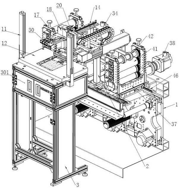
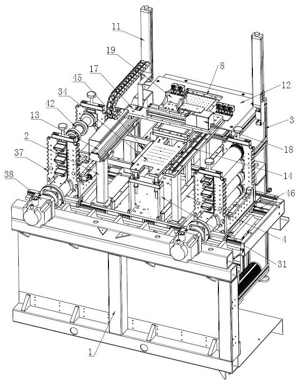
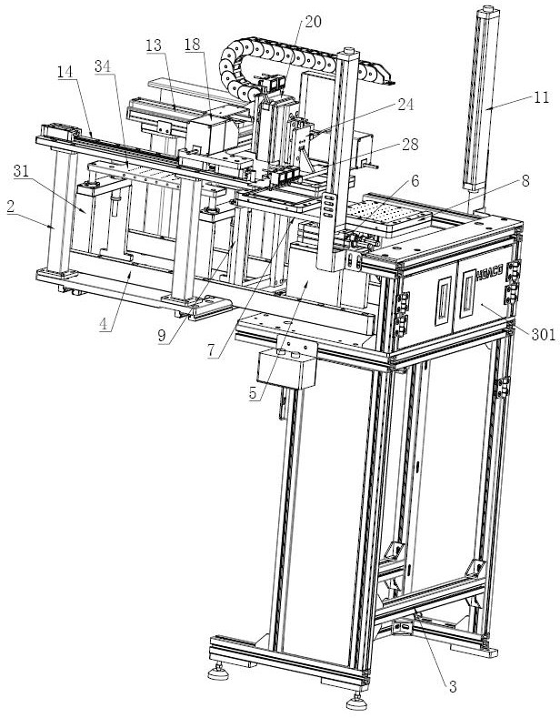
[0074] As shown in FIG. 1 to FIG. 6, the present embodiment provides a microneedle patch transfer device, including a rack 1, the rack 1

[0075] As shown in Figure 1 to Figure 4, Figure 7 to Figure 11, the material feeding mechanism includes a feeding rack body 3, and the feeding rack body 3 is on the upper

[0080] In the present embodiment, the sheet positioning tray 8 abuts against the material rotating plate 7 and is provided with a suction hole for the first sheet

[0095] The first buffer mechanism includes a second guide rail 22 vertically fixed on the third mounting plate 21, on the second guide rail 22

[0100] In this embodiment, the material suction plate 29 and the sealing cover plate 30 are annular structures, which saves materials.

[0105] The third material adsorption hole 3401 provided on the adhesive support plate 34 realizes the adsorption of the microneedle patch and ensures that the microneedle

[0106] As shown in FIG. 19, in the present embodiment, the adhes...


PUM


Abstract

The invention belongs to the technical field of microneedle patch processing, and provides a microneedle patch transfer device, including a frame, on which a feeding base platform is arranged, and an adhesive supporting plate is arranged on the feeding base platform And a material transfer mechanism for transferring and placing the microneedle patch on the bonding pallet, the upstream of the material transfer mechanism is provided with a material feeding mechanism for realizing microneedle patch loading; The downstream of the feeding base platform is provided with a material belt traction conveying mechanism, and the side of the material belt traction conveying mechanism facing the feeding base platform is provided with a material belt guide roller, and the material belt guide roller is attached to the discharge side of the bonding pallet, slightly When the needle patch is placed on the bonding pallet, one side of the microneedle patch is placed outside the discharge side of the bonding pallet. The invention can realize efficient transfer of the microneedle patch on the sticky material tape, and the pasting is accurate and orderly, can ensure that the microneedle patch is pasted smoothly, and effectively avoids the generation of air bubbles, thereby ensuring the safety of the microneedle patch Processing quality is not affected.

Description

A microneedle patch transfer device technical field [0001] The present invention relates to the technical field of microneedle patch processing, in particular to a microneedle patch transfer device. Background technique According to experts, drug transdermal only needs a very small hole to achieve, but at present in the medical treatment, beauty industry, to In the past, a common needle was used to pierce the dermis below the dermis to deliver the medicine, which not only caused pain but also caused infection. The emergence of microneedle patches, get Widely accepted and recognized by people, after the microneedle patch is attached to the human skin, its nanoscale microneedles can pierce the skin and penetrate into the stratum corneum. Micro-channels are formed, and the drugs or cosmetic active ingredients in the micro-needles (such as hyaluronic acid or various added anti-wrinkle, whitening and other effective ingredients) points) along the microchannel to reach th...

Claims


Application Information

Patent Timeline
Patent Type & Authority Patents(China)
IPC IPC(8): B65H23/26B65H20/02B65H37/04B65H5/08
CPCB65H23/26B65H20/02B65H37/04B65H5/08B65H2701/1133B65H2701/1131
Inventor 宋光辉王玉亮刘龙凯
Owner SHANDONG HOACO AUTOMATION TECH
Why Eureka
Try Eureka