
Cable laying equipment

A cable laying and equipment technology, applied in cable laying equipment, printing, stamping and other directions, can solve the problems of difficult to ensure accurate measurement distance, left and right deviation of the movement direction of the winding wheel, and increase the difficulty of cable laying, so as to reduce the laying difficulty. , to avoid the effect of consuming physical strength and reducing the number of marks

Pending Publication Date: 2021-08-13
芜湖市科特电线电缆有限公司
View PDF1 Cites 0 Cited by
  • Summary
  • Abstract
  • Description
  • Claims
  • Application Information

AI Technical Summary

Problems solved by technology

[0006] 2. When laying cables on the ground, the workers fix the free end of the cables, and then the workers push the cable winding wheel, so that the cables are transferred from the winding wheel to the ground. In this way, the workers are pushing the winding wheel. When the reel is rolled, the movement direction of the reel will shift left and right, which increases the difficulty of laying the cable; and in this way, after the cable is laid, it is necessary to measure the use distance of the cable, and the measurement by the worker increases the difficulty of laying the cable. The labor intensity of the workers, and because the cables are crooked, it is difficult to ensure accurate distance measurement

Method used


Image

  • Cable laying equipment
  • Cable laying equipment
  • Cable laying equipment

Examples


Embodiment Construction

[0045] The technical solutions of the present invention will be further described below in conjunction with the accompanying drawings and through specific implementation methods.

[0046] Wherein, the accompanying drawings are only for illustrative purposes, showing only schematic diagrams, rather than physical drawings, and should not be construed as limitations on this patent; in order to better illustrate the embodiments of the present invention, some parts of the accompanying drawings will be omitted, Enlarged or reduced, does not represent actual product size.

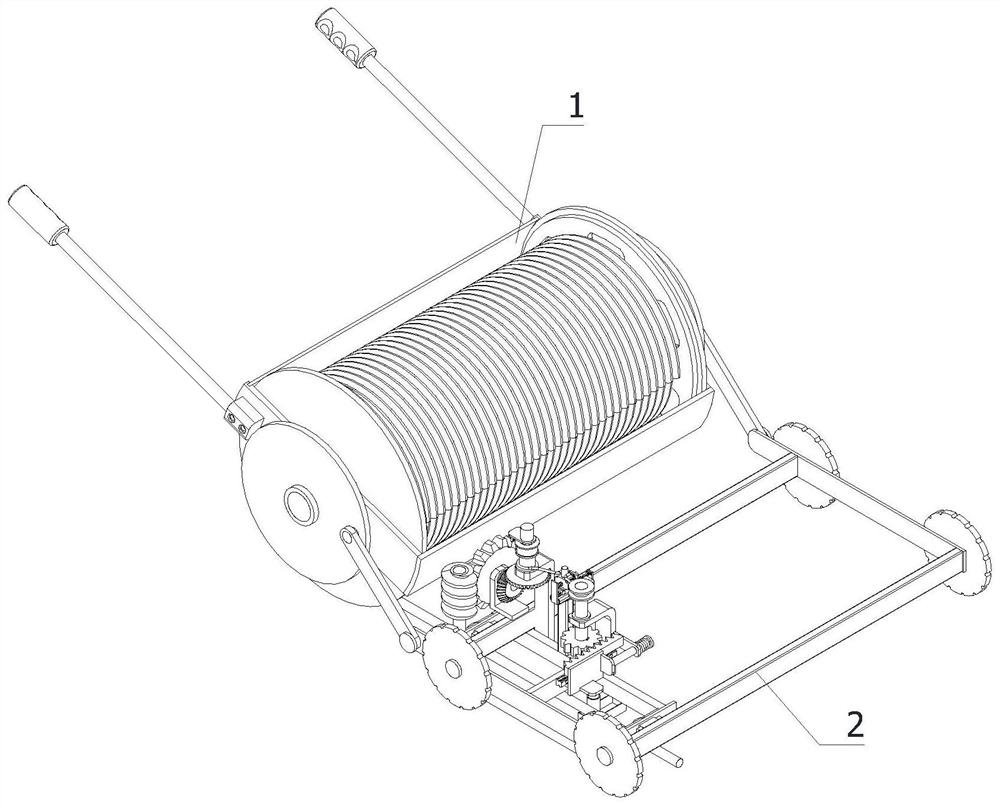
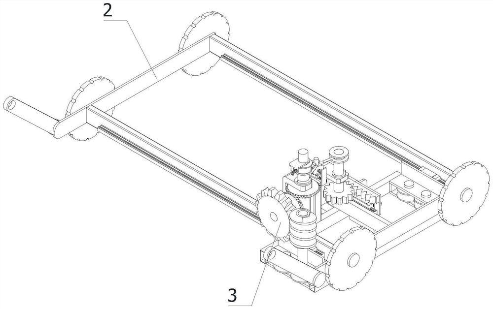
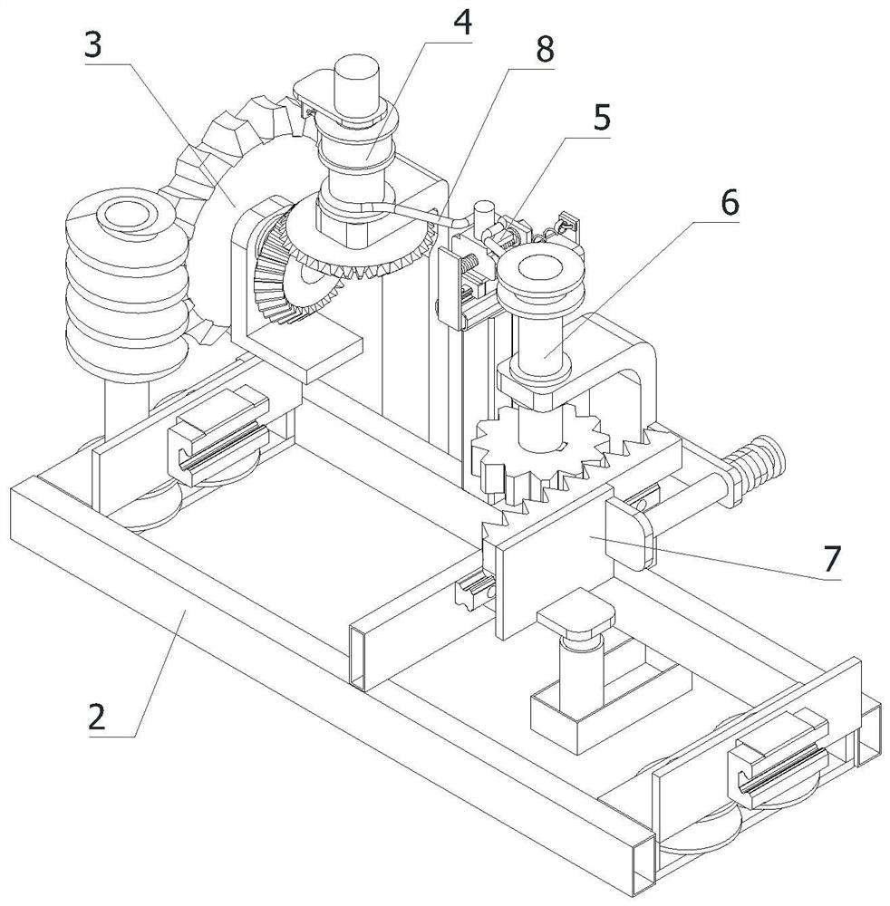
[0047] refer to Figure 1 to Figure 13 The shown cable laying equipment includes a mobile car 1, a wire car 2, a transmission mechanism 3, a positioning release mechanism 4, a scale adjustment mechanism 5, a pulling mechanism 6, an engraving mechanism 7 and a pull rope 8. The mobile car 1 is placed on On the ground, the wire car 2 is fixedly installed on the mobile car 1, the wire car 2 is in contact with the gro...


PUM


Abstract

The invention relates to the field of cable laying, in particular to cable laying equipment. The cable laying equipment comprises a moving vehicle, a cable guiding vehicle, a transmission mechanism, a positioning and releasing mechanism, an engraving distance adjusting mechanism, a pulling mechanism, a marking mechanism and a pull rope. According to the cable laying equipment, by clamping a cable winding wheel into the moving vehicle and pulling the moving vehicle by a worker, the moving vehicle drives the cable winding wheel to rotate, so that the cable rotates on the ground, the moving position of the cable winding wheel is conveniently controlled, left-right deviation of the moving direction of the winding wheel is avoided, and the laying difficulty of the cable is reduced; and moreover, the free end of the cable is fixed, the cable will pass through the cable guiding vehicle; and through the combination of the transmission mechanism, the positioning and releasing mechanism and the pulling mechanism, the marking mechanism is pulled to move once when the cable moves for a certain distance every time, and then the cable is marked, so that the situation that a worker measures the length of the laid cable subsequently is avoided, the worker only needs to count the marking number, and a large amount of time of the worker is saved.

Description

technical field [0001] The invention relates to the field of cable laying, in particular to a cable laying equipment. Background technique [0002] When laying cables, during ground construction, it is often necessary to lay cables on the ground. Often when laying cables on the ground, workers fix the free end of the cables, and then push the cable rewinding wheel through the workers to make the cables roll from the reel. Go to the ground, and in this way, when the worker pushes the take-up wheel, the movement direction of the take-up wheel will deviate left and right, which increases the difficulty of cable laying. [0003] my country's patent application number: CN202010044007.9; discloses a cable laying equipment and a cable laying method. When the handle rotates with the housing, one of the ratchets cooperates with the pawl to make the handle rotate in one direction with the ratchet. When a ratchet is matched with the pawl, the ratchet can be unidirectionally rotated in ...

Claims


Application Information

Patent Timeline
IPC IPC(8): B65H75/42B65H75/44H02G1/06B41K3/62
CPCB41K3/62B65H75/425B65H75/4402B65H75/4457B65H75/4497B65H2701/34H02G1/06
Inventor 潘飞梁欣冯林静
Owner 芜湖市科特电线电缆有限公司
Learn More