Eureka AIR delivers breakthrough ideas for toughest innovation challenges, trusted by R&D personnel around the world.

Electric piston pump type foam generator

A foam generator and piston pump technology, applied in the field of foam pumps, can solve problems such as unsmooth liquid intake, uneven foaming, and large changes in gas-liquid ratio, so as to achieve easy installation and replacement, prolong the service life of the machine, and The effect of a small change in liquid ratio

Inactive Publication Date: 2021-08-13
东莞奥立唯科技有限公司
View PDF0 Cites 0 Cited by
  • Summary
  • Abstract
  • Description
  • Claims
  • Application Information

AI Technical Summary

Problems solved by technology

[0002] The existing foam generator utilizes the motor to drive the connecting rod through the eccentric wheel to drive the piston to work, so that the inhaled liquid (such as soap, detergent, etc., which can make foam) is made into a foam state output, but the existing foam generator The liquid inlet and air inlet are controlled by the same piston, the installation is limited, the liquid inlet and air inlet are not coherent, the initial liquid inlet is not smooth, the gas-liquid ratio entering the foam generator changes greatly, and the control is not precise, resulting in uneven foaming. At the same time, a hose is used for the air outlet connection. Due to the large change in the volume of the hose, the foam quality is unstable and affects the use of the foam generator.

Method used


Image

  • Electric piston pump type foam generator
  • Electric piston pump type foam generator
  • Electric piston pump type foam generator

Examples


Embodiment Construction

[0033] The following will clearly and completely describe the technical solutions in the embodiments of the present invention with reference to the accompanying drawings in the embodiments of the present invention. Obviously, the described embodiments are only some of the embodiments of the present invention, not all of them. Based on the embodiments of the present invention, all other embodiments obtained by persons of ordinary skill in the art without making creative efforts belong to the protection scope of the present invention.

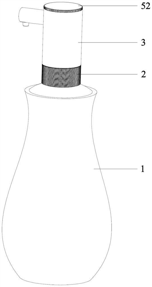
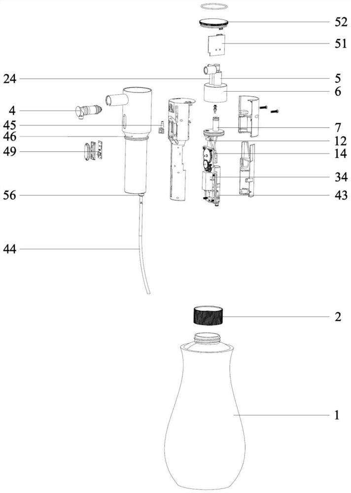
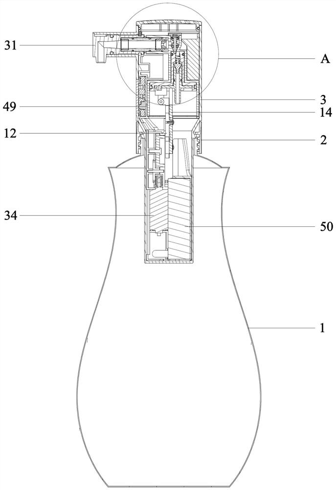
[0034] Such as Figure 1 to Figure 9An electric piston pump foam generator according to the present invention includes a liquid tank 1 and a pump body 3 installed on the top 1 of the liquid tank through a screw cap 2 of the liquid tank. The top of the pump body 3 is connected with a detachable and replaceable nozzle assembly 4. The upper part of the pump body 3 is provided with a liquid cylinder 5 communicating with the nozzle assembly 4. The bot...


PUM


Abstract

The invention discloses an electric piston pump type foam generator which comprises a liquid tank and a pump body installed at the top of the liquid tank through a liquid tank threaded cover. The top of the pump body is connected with a detachable and replaceable nozzle assembly, the upper portion in the pump body is provided with a hydraulic cylinder communicating with the nozzle assembly, and the bottom of the hydraulic cylinder is connected with an air cylinder. An integrated piston is arranged in the middle in the pump body and comprises a hydraulic cylinder piston arranged in the hydraulic cylinder in a sleeved mode and an air cylinder piston arranged in the air cylinder in a sleeved mode, a first piston assembly is installed in the middle in the pump body, and a second piston assembly is installed on the first piston assembly through a connecting column. A driving device for driving the first piston assembly to move up and down is installed at the lower portion in the pump body, and a liquid inlet pipeline arranged in the hydraulic cylinder piston in a sleeved mode is arranged on the top of the second piston assembly. According to the electric piston pump type foam generator, the whole liquid inlet, gas inlet, liquid outlet, gas outlet and gas-liquid mixing process is coherent and smooth, the gas-liquid proportion change is small, and the foam outlet quality is stable.

Description

technical field [0001] The invention relates to the technical field of foam pumps, in particular to an electric piston pump type foam generator. Background technique [0002] The existing foam generator utilizes the motor to drive the connecting rod through the eccentric wheel to drive the piston to work, so that the inhaled liquid (such as soap, detergent, etc., which can make foam) is made into a foam state output, but the existing foam generator The liquid inlet and air inlet are controlled by the same piston, the installation is limited, the liquid inlet and air inlet are not coherent, the initial liquid inlet is not smooth, the gas-liquid ratio entering the foam generator changes greatly, and the control is not precise, resulting in uneven foaming. At the same time, a hose is used for the air outlet connection. Due to the large change in the volume of the hose, the foaming quality is unstable, which affects the use of the foam generator. Therefore, in order to avoid th...

Claims


Application Information

Patent Timeline
IPC IPC(8): F04B17/03F04B53/00F04B53/10F04B53/16F04B53/20
CPCF04B17/03F04B53/00F04B53/10F04B53/16F04B53/162F04B53/20
Inventor 周贤智董小友
Owner 东莞奥立唯科技有限公司
Why Eureka
Eureka Blog
Learn More