Calibration method of laser radar and camera

A technology of laser radar and calibration method, which is applied in the field of laser radar and camera calibration, can solve the problems of low calibration accuracy, low precision, and difficult production, and achieve the effect of high labeling accuracy

Active Publication Date: 2021-08-13
AUTOCORE INTELLIGENT TECH NANJING CO LTD
View PDF4 Cites 7 Cited by
  • Summary
  • Abstract
  • Description
  • Claims
  • Application Information

AI Technical Summary

Problems solved by technology

When using a three-dimensional calibration plate, not only is it difficult to make, the cost is high, but the calibration accuracy is not high; , and the error of manual operation, this method needs to select more points, and the operation is complicated and the accuracy is not high

Method used


Image

  • Calibration method of laser radar and camera
  • Calibration method of laser radar and camera
  • Calibration method of laser radar and camera

Examples


Embodiment Construction

[0026] The calibration method of the lidar and the camera of the present embodiment comprises the following steps:

[0027] Step 1, select the calibration board, for example: select the calibration board of 49cm*49cm. Stick the ArUco code on the surface of the calibration board, and fix the calibration board in front of the camera. The ArUco code calibration plate is the most commonly used calibration plate, and the four corner points of the calibration plate can be easily obtained through the ArUco code. When in use, fix the calibration plate, in front of the camera, to ensure that the surrounding area of ​​the calibration plate is relatively open and there are few noises.

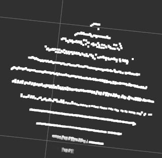
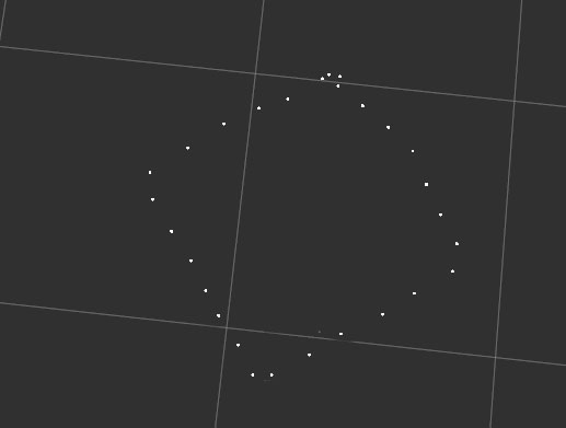
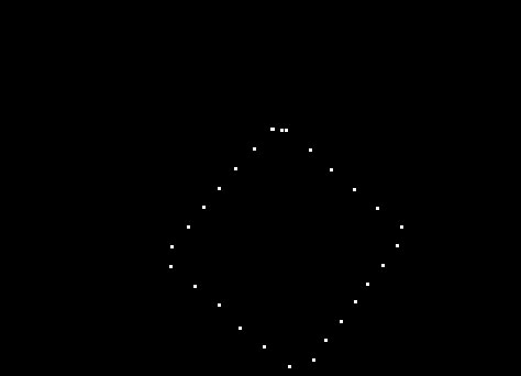
[0028] Step 2: The lidar acquires N frames of point cloud data including the calibration plate, and records the coordinates of each point in each frame of point cloud data and its corresponding ray id. Due to the inherent error of lidar, there will be a slight deviation in each scan for the same positio...


PUM


Abstract

The invention relates to a calibration method of a laser radar and a camera, and the method comprises the following steps: enabling the laser radar to obtain N frames of point cloud data comprising a calibration board, eliminating the random error of the laser radar, and finding out the edge points of the calibration board; setting a transformation matrix between the calibration plate and the radar coordinate system as a T1 pseudo camera coordinate system, transforming the edge points of the calibration plate to the pseudo camera coordinate system, and projecting the edge points to an imaging plane of a pseudo camera to obtain a projection image; finding a 2d coordinate of an angular point of the calibration plate in a pseudo camera coordinate system from the projection image; and obtaining 3d coordinates of the angular points of the calibration plate in the camera coordinate system, thereby obtaining a conversion matrix T2 between the camera coordinate system and the pseudo camera coordinate system, and further obtaining a conversion matrix T = T2-1 * T1 between the laser radar coordinate system and the camera coordinate system. According to the method, random errors caused by laser radar scanning can be eliminated, so that the marking precision is improved.

Description

technical field [0001] The invention relates to a laser radar and camera calibration method, which belongs to the technical field of automatic driving. Background technique [0002] Camera and lidar are two important sensors in unmanned vehicles. They provide unmanned vehicles with the ability to perceive the surrounding environment. Since each sensor has its own limitations, for example, cameras cannot obtain depth information, and lidar cannot obtain The color information of the target. In practical applications, multiple sensors are often used to fuse their perception results. The perception results of the same target are obtained in different coordinate systems. Therefore, in order to complete the fusion of the camera and the lidar, it is necessary to know the conversion relationship between the different coordinate systems of the camera and the lidar, that is, to calibrate the camera and the lidar. [0003] As far as the applicant knows, the existing calibration metho...

Claims


Application Information

Patent Timeline
Patent Type & Authority Applications(China)
IPC IPC(8): G01S7/497G06T7/80
CPCG01S7/497G06T7/80
Inventor 苏畅张旸陈诚
Owner AUTOCORE INTELLIGENT TECH NANJING CO LTD
Why Eureka
Try Eureka