Methods and patterning devices and apparatuses for measuring focus performance of a lithographic apparatus, device manufacturing method

A performance and lithography technology, applied in the direction of microlithography exposure equipment, optomechanical equipment, photoplate making process exposure equipment, etc., can solve the problems of weakening diffraction efficiency and weakening signal strength

Pending Publication Date: 2021-08-13
ASML NETHERLANDS BV
View PDF15 Cites 0 Cited by
  • Summary
  • Abstract
  • Description
  • Claims
  • Application Information

AI Technical Summary

Problems solved by technology

This reduces the diffraction efficiency and thus the signal strength that can be used for focusing measurements

Method used


Image

  • Methods and patterning devices and apparatuses for measuring focus performance of a lithographic apparatus, device manufacturing method
  • Methods and patterning devices and apparatuses for measuring focus performance of a lithographic apparatus, device manufacturing method
  • Methods and patterning devices and apparatuses for measuring focus performance of a lithographic apparatus, device manufacturing method

Examples


Embodiment Construction

[0032] Before describing embodiments of the invention in detail, it is instructive to present an example environment in which embodiments of the invention may be practiced.

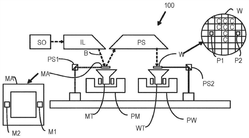
[0033] figure 1 A lithographic apparatus 100 comprising a source module SO is schematically depicted according to an embodiment of the present invention. The equipment includes:

[0034] - an illumination system (illuminator) IL configured to condition a radiation beam B (eg EUV radiation);

[0035] - a support structure (eg mask table) MT configured to support a patterning device (eg mask or reticle) MA and connected to first positioning means PM configured to accurately position said patterning device;

[0036] - a substrate table (e.g. a wafer table) WT configured to hold a substrate (e.g. a resist-coated wafer) W and connected to a second positioner configured to accurately position the substrate device PW; and

[0037] - a projection system (e.g. a reflective projection system) PS configured to p...


PUM


Abstract

Disclosed is a method for selecting a structure for focus monitoring. The method comprises: simulating a Bossung response with focus of a focus dependent parameter, for one or more different structures; and selecting a structure for focus monitoring in a manufacturing process based on the results of said simulating step. The simulating step may be performed using a computational lithography simulation.

Description

[0001] Cross References to Related Applications [0002] This application claims priority to US Application No. 62 / 787,973, filed January 3, 2019, which is incorporated herein by reference in its entirety. technical field [0003] The present invention relates to inspection apparatus and methods that can be used to perform metrology, for example in the manufacture of devices by photolithography. The invention also relates to such a method for monitoring focus parameters during lithography. Background technique [0004] A lithographic apparatus is a machine that applies a desired pattern onto a substrate, usually onto a target portion of the substrate. A lithographic apparatus may be used, for example, in the manufacture of integrated circuits (ICs). In this case, a patterning device (which is alternatively referred to as a mask or reticle) can be used to create the circuit pattern to be formed on the individual layers of the IC. This pattern can be transferred onto a targ...

Claims


Application Information

Patent Timeline
IPC IPC(8): G03F7/20
CPCG03F7/70641G03F7/70525
Inventor C·R·K·C·亨纳克斯弗兰克·斯塔尔斯
Owner ASML NETHERLANDS BV
Why Eureka
Try Eureka