Saw blade clamping guide device and saw blade clamping guide method

A technology of a guide device and a saw blade, which is applied in the direction of sawing machine device, sawing machine tool, metal sawing equipment, etc., can solve the problems of increasing labor cost, affecting production efficiency, and high fixture cost, and reducing the degree and structure of human intervention. Reasonable and ingenious design, the effect of reducing production costs

Active Publication Date: 2022-04-22
DONGGUAN YISONG CNC TECH
View PDF6 Cites 0 Cited by
  • Summary
  • Abstract
  • Description
  • Claims
  • Application Information

AI Technical Summary

Problems solved by technology

The existing CNC sawing machine mainly uses a guide device with a fixed positioning groove to achieve the purpose of positioning the saw blade. However, when the saw blade is cutting, it will rub against the positioning groove. After a certain period of use, the positioning groove will not work well. The positioning of the saw blade makes the saw blade prone to slipping or displacement during cutting, and the direct replacement of the fixture is expensive and wasteful; different specifications of the saw blade need to be equipped with different specifications of the fixture, and the versatility of the fixture is low, resulting in the production cost of the CNC sawing machine stay high;
[0003] In addition, the existing CNC sawing machine is not very intelligent in clamping and replacing the saw blade. When changing the cutting station or taking out the saw blade, it is difficult to realize the automatic clamping of the saw blade, resulting in too much human intervention. On the one hand, it increases Labor costs, on the other hand affect production efficiency

Method used


Image

  • Saw blade clamping guide device and saw blade clamping guide method
  • Saw blade clamping guide device and saw blade clamping guide method
  • Saw blade clamping guide device and saw blade clamping guide method

Examples


Embodiment Construction

[0062] The following will clearly and completely describe the technical solutions in the embodiments of the present invention with reference to the accompanying drawings in the embodiments of the present invention. Obviously, the described embodiments are only some, not all, embodiments of the present invention. Based on the embodiments of the present invention, all other embodiments obtained by persons of ordinary skill in the art without making creative efforts belong to the protection scope of the present invention.

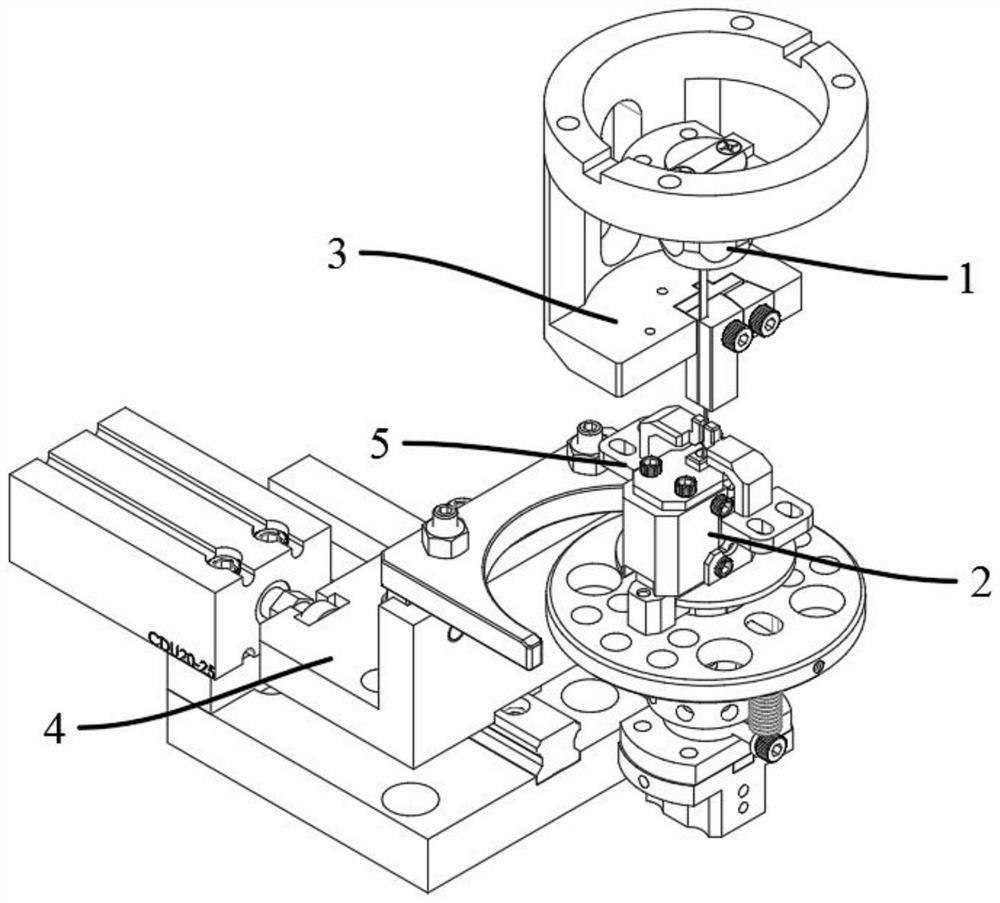
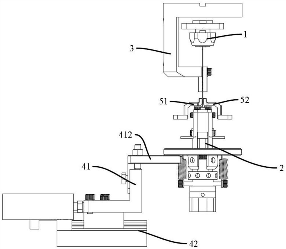
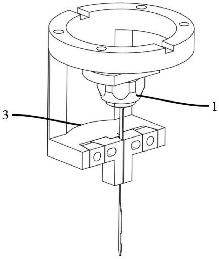
[0063] see Figure 1 to Figure 10According to another aspect of the present invention, an embodiment of the present invention provides a saw blade clamping and guiding device according to one aspect of the present invention, including:

[0064] Upper clamp assembly 1, which can clamp the upper end of the saw blade;

[0065] Lower clamp assembly 2, which can clamp the lower end of the saw blade;

[0066] Saw blade guide assembly 3, which can guide and positio...


PUM


Abstract

The invention provides a saw blade clamping guide device and a saw blade clamping guide method, wherein the saw blade clamping guide device includes: an upper clamp assembly capable of clamping the upper end of the saw blade; a lower clamp assembly capable of clamping The lower end of the saw blade; the saw blade guide assembly, which can guide and position the saw blade; the lower clamp release assembly, which can control the lower clamp assembly to clamp or release the lower end of the saw blade. The invention has a reasonable and ingenious structure design, realizes the clamping and loosening of the saw blade, and can overcome the wear of the saw blade or the guide groove by adjusting the size of the gap between the guide bump and the guide groove, and does not need to be equipped with clamps of different specifications. Improve the versatility of the device and effectively reduce the production cost of the CNC sawing machine; in addition, this structural design ensures that the saw blade is lifted up and down when the machine is processing the bridge position, so as to smoothly pass the bridge position. On the one hand, the labor cost is reduced, and on the other hand, the production is improved efficiency. It solves the problem that the existing numerical control sawing machine is not highly intelligent in clamping the saw blade and replacing the saw blade.

Description

technical field [0001] The invention relates to the technical field of sawing machine equipment, in particular to a saw blade clamping and guiding device and a saw blade clamping and guiding method. Background technique [0002] The CNC sawing machine has the advantages of fast processing speed and low purchase cost, and is widely used in the field of machining technology. When the CNC sawing machine is working, the staff first needs to place the object to be cut on the band sawing machine, and then clamp the saw blade with a general clamp to The anti-saw blade moves when cutting the cutting material. The existing CNC sawing machine mainly uses a guide device with a fixed positioning groove to achieve the purpose of positioning the saw blade. However, when the saw blade is cutting, it will rub against the positioning groove. After a certain period of use, the positioning groove will not work well. The positioning of the saw blade makes the saw blade prone to slipping or dis...

Claims


Application Information

Patent Timeline
Patent Type & Authority Patents(China)
IPC IPC(8): B23D55/08B23D61/12
CPCB23D55/082B23D61/12
Inventor 池益慧
Owner DONGGUAN YISONG CNC TECH
Why Eureka
Try Eureka