Drill rod power head device, circulating device and drilling machine

A technology of circulation device and power head, which is applied to rotary drilling rigs, drilling tools, earthwork drilling and mining, etc., and can solve problems such as difficulty in drilling wells

Active Publication Date: 2021-08-17
BC P INC CHINA NAT PETROLEUM CORP +1
View PDF7 Cites 0 Cited by
  • Summary
  • Abstract
  • Description
  • Claims
  • Application Information

AI Technical Summary

Problems solved by technology

[0008] The purpose of the present invention is to provide a drill pipe power head device, circulation device and drilling rig to solve the technical problem of difficulty in drilling and forming holes caused by the need to replace different drilling rigs for the same well in complex lithology areas

Method used


Image

  • Drill rod power head device, circulating device and drilling machine
  • Drill rod power head device, circulating device and drilling machine
  • Drill rod power head device, circulating device and drilling machine

Examples


Embodiment 1

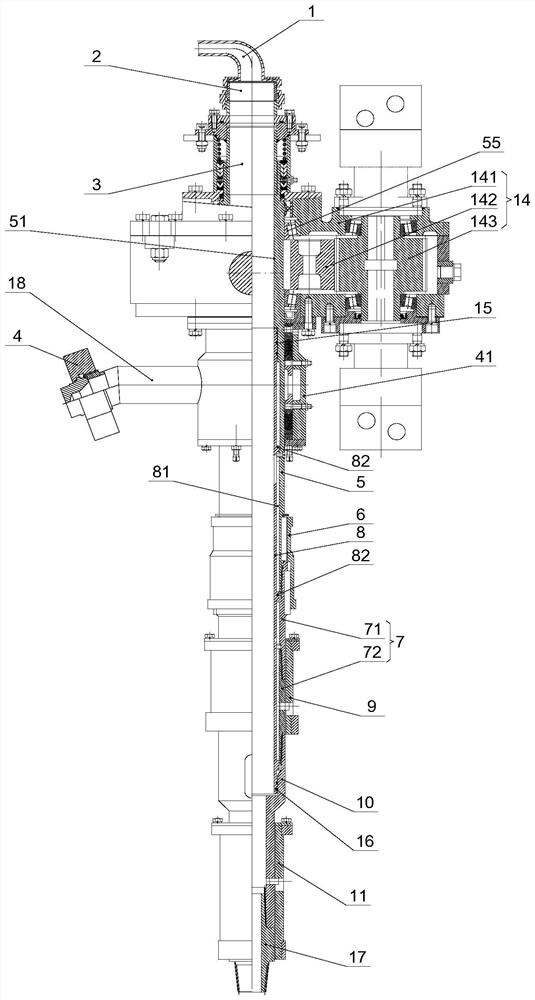
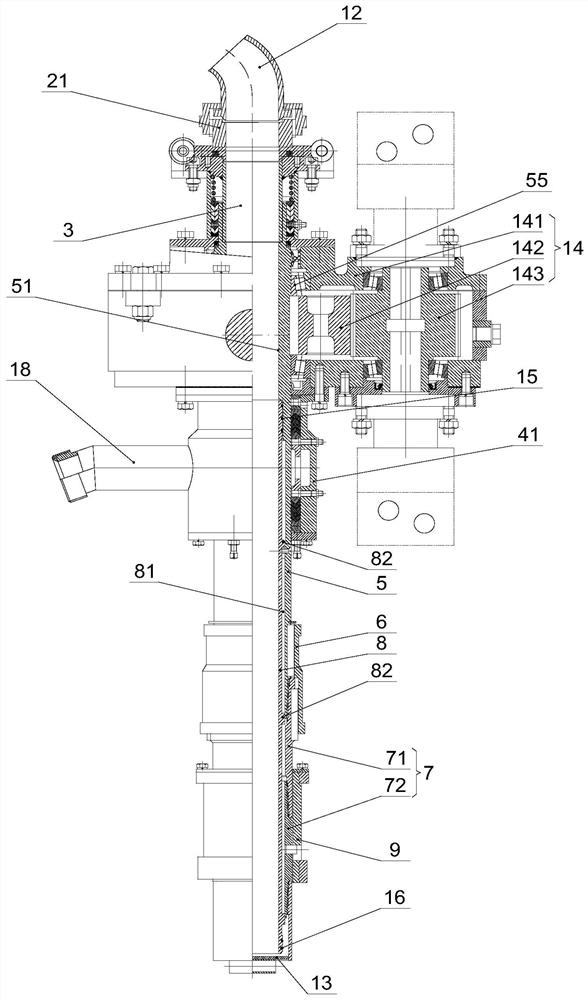
[0062] The invention provides a drill pipe power head device, such as figure 1 , figure 2 with Figure 5 As shown, the drilling head unit includes a power mechanism 14 and a circulation device; the circulation device includes: a center pipe 5, an inner pipe 8 and an air intake pipe 18; the center pipe 5 is installed on the power mechanism 14, and the power mechanism 14 can drive the center pipe 5 rotation; the inner pipe 8 is arranged in the central pipe 5, and the first annular space 81 is arranged between the inner pipe 8 and the central pipe 5, and the upper end of the inner pipe 8 is sealed with the inner wall of the central pipe 5; the air inlet pipe 18 and the first ring Hole 81 communicates; In the case that the lower end of central pipe 5 is connected to the positive circulation drill pipe, the central hole of inner pipe 8 communicates with the central hole of positive circulation drill pipe; In the case of circulating drill pipe, the first annulus 81 communicates w...

Embodiment 2

[0092] The present invention provides a circulation device, which is applied to the above-mentioned drill pipe head device, such as figure 1 , figure 2 with Figure 5 As shown, the circulation device includes: a central pipe 5, an inner pipe 8 and an air intake pipe 18; the inner pipe 8 is arranged in the central pipe 5, and a first annular space 81 is provided between the central pipe 5 and the inner pipe 8; the air intake pipe 18 It communicates with the first annulus 81; when the lower end of the center pipe 5 and the lower end of the inner pipe 8 are connected to the reverse circulation drill pipe, the first annulus 81 communicates with the drill pipe annulus of the reverse circulation drill pipe, and the inner pipe The center hole of 8 communicates with the center hole of the inner pipe of the reverse circulation drill pipe; when the lower end of the center pipe 5 is connected with the positive circulation drill pipe, the center hole of the inner pipe 8 communicates wit...


PUM


Abstract

The invention provides a drill rod power head device, a circulating device and a drilling machine. The drill rod power head device comprises a power mechanism and the circulating device. The circulating device comprises a central pipe, an inner pipe and an air inlet pipe. The central pipeis installed on the power mechanism, and the power mechanism can drive the central pipe to rotate; the inner pipe is arranged in the central pipe, a first annular space is formed between the inner pipe and the central pipe, and the upper end of the inner pipe is in sealing fit with the inner wall of the central pipe; the air inlet pipe communicates with the first annular space; under the condition that the lower end of the central pipe is connected with a direct circulation drill rod, a central hole of the inner pipe communicates with a central hole of the direct circulation drill rod; and under the condition that the lower end of the central pipe and the lower end of the inner pipe are connected with a reverse circulation drill rod, the first annular space communicates with a drill rod annulus of the reverse circulation drill rod, and the central hole of the inner pipe communicates with an inner pipe central hole of the reverse circulation drill rod. According to the drill rod power head device, the circulating device and the drilling machine, the technical problem that drilling and hole forming are difficult due to the fact that different drilling machines need to be replaced for the same well in a complex lithologic area is solved, and an integrated forward and reverse circulation drilling machine is achieved.

Description

technical field [0001] The invention relates to the field of drilling equipment, in particular to a drill pipe power head device, a circulation device and a drilling rig. Background technique [0002] The abundance of exploration in the basins where some oilfields are located has increased year by year, and the exploration scope has gradually expanded to radiate to surrounding areas. Some basins are located in high latitude areas, extremely cold in winter, the coldest is below -40°C, 75% of the surface is covered by volcanic rocks, multi-phase volcanic eruptions, weathering, denudation, water erosion, etc., fluctuate greatly, and there are gullies and river valley. The surface lithology is diverse, mainly composed of different types of volcanic lava, quicksand, sandy gravel, larger gravel and clay. [0003] The vertical and lateral changes of the surface lithology in some basins are relatively complex, and there are multiple lithological interlayers in one well, and one dr...

Claims


Application Information

Patent Timeline
Patent Type & Authority Applications(China)
IPC IPC(8): E21B3/02E21B12/00
CPCE21B3/02E21B12/00
Inventor 王全义辛志多刘伟张伟李龙江丁洪文
Owner BC P INC CHINA NAT PETROLEUM CORP
Why Eureka
Try Eureka