Overflow and blowout prevention drilling device and method thereof

A drilling device and anti-overflow technology, applied in drilling equipment and methods, wellbore/well valve devices, drill pipes, etc., can solve problems such as the lack of anti-overflow and blowout functions.

Active Publication Date: 2020-12-25
LANZHOU INST OF TECH
View PDF13 Cites 0 Cited by
  • Summary
  • Abstract
  • Description
  • Claims
  • Application Information

AI Technical Summary

Problems solved by technology

[0005] Drilling rig currently shown does not have overflow and blowout protection

Method used


Image

  • Overflow and blowout prevention drilling device and method thereof
  • Overflow and blowout prevention drilling device and method thereof
  • Overflow and blowout prevention drilling device and method thereof

Examples


Embodiment 1

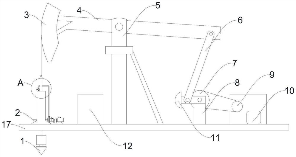
[0049] Please refer to Figure 1-Figure 7 , the present embodiment provides an overflow and blowout prevention drilling device, which has the function of preventing overflow and blowout.

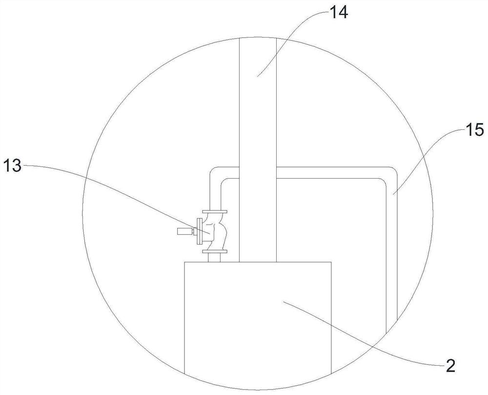
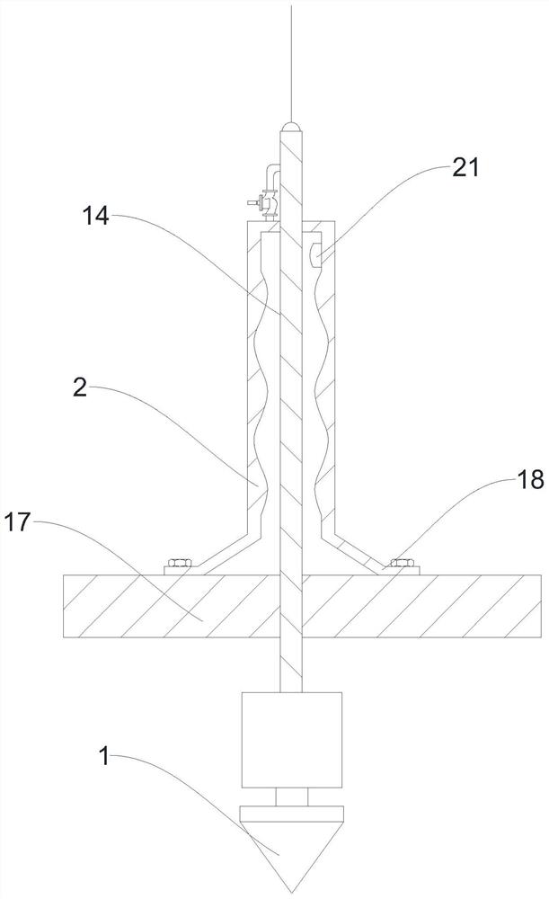
[0050] A drilling device for preventing overflow and blowout, comprising a horizontally placed drilling machine base plate 17, and also includes a fixed support rod 5, the above-mentioned fixed support rod 5 is arranged on the upper side of the above-mentioned drilling machine base plate 17, and the above-mentioned fixed support rod The upper side of the pendulum 5 is horizontally hinged with a pendulum 4, one end of the above-mentioned pendulum 4 is connected with a drilling main engine, the other end of the above-mentioned pendulum 4 is connected with a power assembly that drives it to swing, and the lower side of the above-mentioned drilling main engine 3 is provided with The drill rod 14 that cooperates with it, the lower side of the above-mentioned drill rod 14 runs through the lower si...

Embodiment 2

[0069] Please refer to Figure 1-Figure 7 , the present invention provides a method for realizing a drilling device for preventing overflow and blowout, comprising the above-mentioned drilling device, comprising the following steps:

[0070] Drilling process: connect the power supply of the power assembly, the power assembly drives the pendulum 4 to swing, and the pendulum 4 drives the main drilling machine to swing during the swinging process. to punch holes;

[0071] Level 1 anti-overflow: When the drill bit 1 is drilling, the internal fluid pressure gushes outwards when the pressure of the internal fluid is too high. The second pressure sensor 20 transmits the signal to the central processing module 12, the central processing module 12 inflates the expansion air bag 19, and the expansion air bag 19 expands the air bag cover 16 to achieve the first-level sealing purpose in the well;

[0072] Secondary anti-overflow: due to the unevenness of the inner area of ​​the wellhead...


PUM


Abstract

The invention provides an overflow and blowout prevention drilling device and a method thereof, and relates to the technical field of oil exploitation equipment. The overflow and blowout prevention drilling device comprises a drilling machine bottom plate, and further comprises a fixing supporting rod, wherein the fixing supporting rod is arranged on the upper side of the drilling machine bottom plate, a pendulum hammer is transversely hinged to the upper side of the fixing supporting rod, one end of the pendulum hammer is connected with a drilling main machine, the other end of the pendulum hammer is connected with a power assembly driving the pendulum hammer to swing, a drill rod matched with the drilling main machine is arranged on the lower side of the drilling main machine, the lowerside of the drill rod penetrates through the lower side of the fixing supporting rod, a drill bit is arranged on the lower side of the drill rod, an overflow prevention cover is arranged on the upperside of the drilling machine bottom plate, the overflow prevention cover is arranged on the drill rod in a sleeving mode, an overflow pipe communicating with an inner cavity of the overflow preventioncover is connected to the overflow prevention cover, and a valve is arranged on the overflow pipe. The implementation method of the overflow and blowout prevention drilling device comprises the stepsof drilling, primary overflow prevention, secondary overflow prevention and blowout prevention. The overflow and blowout prevention drilling device has the function of the overflow and blowout prevention.

Description

technical field [0001] The invention relates to the technical field of oil exploitation equipment, in particular to a drilling device for preventing overflow and blowout and a method thereof. Background technique [0002] Oil extraction refers to the act of digging and extracting oil in places where oil is stored. In the process of oil extraction, oil and gas flow from the reservoir to the bottom of the well, and then rise from the bottom of the well to the wellhead. [0003] Oil extraction technology includes four processes of logging engineering, drilling engineering, oil production engineering and oil and gas gathering and transportation engineering. Drilling engineering plays a very important role in oil and gas development and oil and gas field development. In the construction of an oil and gas field, drilling engineering often It must account for more than 50% of the total investment. The development of an oil and gas field often requires drilling hundreds or even th...

Claims


Application Information

Patent Timeline
Patent Type & Authority Applications(China)
IPC IPC(8): E21B34/08E21B33/06E21B7/00E21B19/087E21B47/06G08B21/24
CPCE21B34/08E21B33/06E21B7/00E21B19/087E21B47/06G08B21/24Y02P70/10
Inventor 王景民薛鹏伟张翔
Owner LANZHOU INST OF TECH
Why Eureka
Try Eureka