Anti-icing structure of inlet guide vane of aero-engine and inlet guide vane

A technology of aero-engines and inlet guide vanes, which is applied in the direction of machines/engines, liquid fuel engines, and parts of pumping devices for elastic fluids, etc., which can solve problems such as engine performance degradation and achieve the effect of maintaining aerodynamic performance

Active Publication Date: 2021-08-17
AECC SHANGHAI COMML AIRCRAFT ENGINE MFG CO LTD +1
View PDF10 Cites 2 Cited by
  • Summary
  • Abstract
  • Description
  • Claims
  • Application Information

AI Technical Summary

Problems solved by technology

[0004] The technical problem to be solved by the present invention is to provide an anti-icing structure for the inlet guide vane of an aeroengine and the inlet guide vane in order to overcome the defect that the engine performance is degraded by the engine anti-icing structure in the prior art.

Method used


Image

  • Anti-icing structure of inlet guide vane of aero-engine and inlet guide vane
  • Anti-icing structure of inlet guide vane of aero-engine and inlet guide vane
  • Anti-icing structure of inlet guide vane of aero-engine and inlet guide vane

Examples


Embodiment Construction

[0049] The present invention is further illustrated below by means of examples, but the present invention is not limited to the scope of the examples.

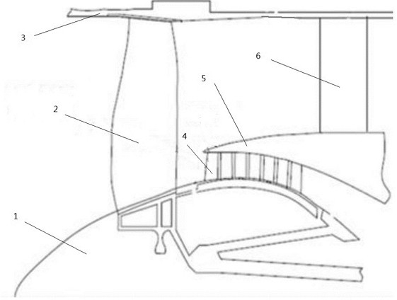
[0050] The embodiment of the present invention provides an anti-icing structure of the inlet guide vane 4 of an aero-engine, such as figure 1 Shown is a schematic diagram of the internal structure of an aero-engine, which includes an air intake cone 1, a fan blade 2, a fan case 3, an inlet guide vane 4, a splitter ring 5 and an outlet guide vane 6, wherein the fan blade 2 is connected to the inlet Air cone 1 , inlet guide vane 4 and outlet guide vane 6 are all arranged downstream of fan blade 2 , and splitter ring 5 is arranged between inlet guide vane 4 and outlet guide vane 6 . The anti-icing structure can be used on the inner icing surface of the aeroengine, especially on the icing surface of the inlet guide vane 4 .

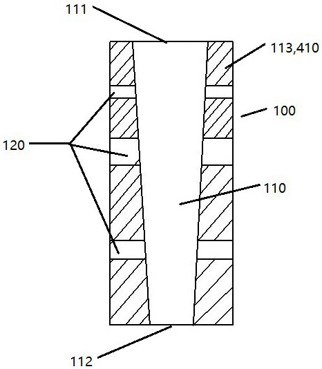
[0051] Such as image 3As shown, the anti-icing structure includes an installation part 100 and a deform...


PUM


Abstract

The invention discloses an anti-icing structure of an inlet guide vane of an aero-engine and the inlet guide vane. The anti-icing structure comprises a mounting part and a deformation part. The inlet guide vane comprises a guide vane body, and the mounting part is arranged on the surface of the guide vane body. The deformation part is arranged in the mounting part. When the temperature around the aero-engine is lower than a first temperature, the deformation part is increased from a first volume to a second volume. When the temperature around the aero-engine is higher than a second temperature, the deformation part is reduced from the second volume to the first volume. By the adoption of anti-icing structure, ice on the surface of the guide vane body can be broken due to deformation of the surface of the guide vane body to which the ice is attached, and the deicing effect is achieved; the influence on the structural strength of the inlet guide vane can be reduced, and the aerodynamic performance of the inlet guide vane is kept; and the volume change of the deformation part is a reversible and repeatable process, so that the part, easy to freeze, of the inlet guide vane can be deiced according to the temperature change.

Description

technical field [0001] The invention relates to the field of aeroengine compressors, in particular to an anti-icing structure of an inlet guide vane of an aeroengine and the inlet guide vane. Background technique [0002] When the aero-engine works under the conditions of high air humidity and temperature close to 0 degrees, the air inlet and the interior of the compressor are prone to icing. The guide vane at the inlet of the aero-engine compressor is a place where ice is easy to form inside the aero-engine and is not easy to remove. Once these parts of the engine freeze, the ice layer will reduce the intake area of ​​the engine, reduce the air flow of the engine, damage the engine performance, and even cause compressor surge in severe cases. If the ice layer breaks into the engine due to engine vibration, the ice will damage the blades, and in severe cases, it will cause the engine to stall and even damage the entire engine. [0003] Nowadays, electric anti-icing systems...

Claims


Application Information

Patent Timeline
Patent Type & Authority Applications(China)
IPC IPC(8): F04D29/54F04D29/56F04D29/02
CPCF04D29/023F04D29/544F04D29/563
Inventor 童辉庞黎刚高修磊陈云永康金
Owner AECC SHANGHAI COMML AIRCRAFT ENGINE MFG CO LTD
Why Eureka
Try Eureka