Fluid conveying system and control method thereof

A fluid conveying system and fluid conveying technology, applied in the pipeline system, gas/liquid distribution and storage, mechanical equipment, etc., can solve the problems of waste of material and liquid, low efficiency, dripping pollution, etc., to ensure efficiency, avoid damage, avoid the effects of

Pending Publication Date: 2021-08-17
蒙牛高科乳制品(马鞍山)有限公司
0 Cites 0 Cited by

AI-Extracted Technical Summary

Problems solved by technology

[0005] Therefore, the technical problem to be solved by the present invention is to overcome the defects of dropping material pollution, waste of material li...

Method used

In the present embodiment, by setting the first air intake control unit 1, sterile air can enter material cylinder 14 by the first air intake control unit 1, and can enter feeding pipeline by feed valve 2; Can make The sterile water in the pipeline from the highest point 4 of the feeding pipeline to the feeding valve 2 is discharged through the fluid output unit 15 and the cleaning return pipeline; A drainage branch is connected between them, and a material top air discharge valve 3 is arranged on the drainage branch, on the one hand, it can speed up the discharge of sterile water in the pipeline from the highest point 4 to the feed valve 2, and on the other hand, it can After the water in the feed pipeline is discharged, the feed liquid in the fluid delivery source 11 can enter the feed pipeline, and the feed liquid pushes the aseptic air to be discharged through the top air discharge valve 3 . Therefore, in this embodiment, the water in the feeding pipeline can be discharged first, thereby avoiding the destruction of the active components in the feed liquid by the sterile hot water, and at the same time avoiding the contamination of the dripping material and the feed liquid due to the thinning of the feed liquid. Waste, which in turn can avoid the impact of fluid output unit dripping on the target performance of fluid delivery and product quality, and can ensure the efficiency of the fluid delivery system because there is no need to wait for a long natural cooling time.
On the basis of above-mentioned embodiment, in a preferred embodiment, feeding pipeline comprises the first branch section that links to each other with fluid delivery source 11, the climbing section that links to each other with the first branch section, and the climbing section In the second branch section connected with the feed valve 2, the top of the climbing section is the highest point 4 of the feeding pipeline, the lowest point of the pipeline is provided on the first branch section, and the first branch section is provided with a feeding valve. The pump 6 and the feed pump 6 are connected in parallel with a bypass branch, and a bypass valve 5 is arranged on the bypass branch. In this embodiment, by setting the climbing pipeline, the second branch section can be set at a higher position, and the space at the high place can be fully utilized, thereby avoiding inconvenience to the s...

Abstract

The invention relates to the technical field of food production, in particular to a fluid conveying system and a control method thereof. The fluid conveying system comprises a fluid conveying target and a fluid conveying source, the fluid conveying target comprises a material cylinder and a fluid output unit, the material cylinder is communicated with a first air inlet control unit and a feeding valve, and the first air inlet control unit is suitable for controlling sterile air to be introduced into the material cylinder. The fluid output unit is communicated with a cleaning return pipeline. The fluid conveying source is provided with a supply valve, and the supply valve is connected with the feeding valve through a supply pipeline. The supply pipeline is provided with a highest point, the highest point is higher than the feeding valve, a drainage branch is connected between the position, close to the feeding valve, of the supply pipeline and the cleaning return pipeline, and a material top air ground discharging valve is arranged on the drainage branch. Water in the supply pipeline can be discharged firstly, so that active ingredients in feed liquid can be prevented from being damaged by sterile hot water, meanwhile, dropping pollution and feed liquid waste caused by dilution of the feed liquid can be avoided, and further, the influence of dropping on fluid conveying target performance and product quality can be avoided.

Application Domain

Pipeline systems

Technology Topic

Process engineeringAir ground +7

Image

  • Fluid conveying system and control method thereof
  • Fluid conveying system and control method thereof
  • Fluid conveying system and control method thereof

Examples

  • Experimental program(3)

Example Embodiment

[0053] Example 1
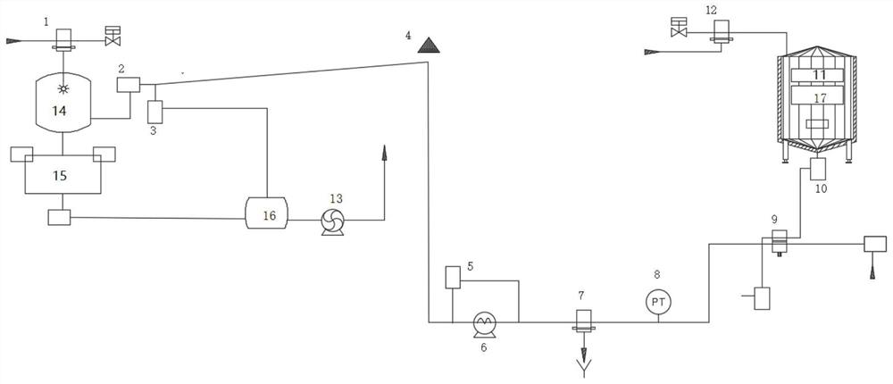
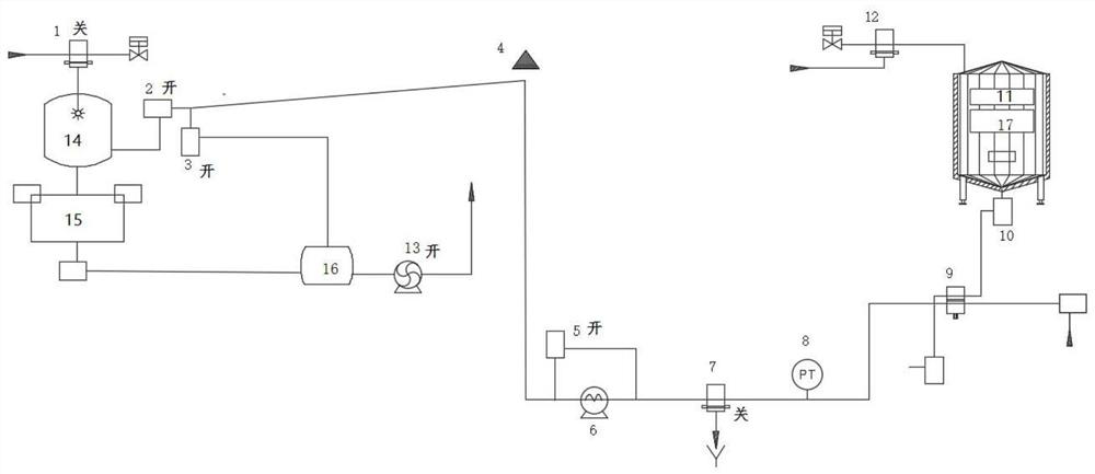
[0054] This embodiment provides a fluid delivery system. In one embodiment, if figure 1 As shown, the fluid delivery system includes a fluid delivery target, a fluid delivery source 11.
[0055] Among them, the fluid delivery target includes a cylinder 14 and a fluid output unit 15, and the cylinder 14 communicates with the first intake control unit 1, the feed valve 2, and the first intake control unit 1 is adapted to the control cylinder to enter a sterile air. The fluid output unit 15 communicates with the cleaning return line; the fluid delivery source 11 is provided with a feeding valve 9, and the feed valve 9 is connected between the feed valve 2; the supply pipe is provided with the highest point 4, the highest The height of the point 4 is higher than the height of the feed valve 2, and the feed pipe is adjacent to the feed valve 2 and the drainage branch is connected between the cleaning reflow line, and the drainage branch is provided with a tape gas row valve 3.
[0056] In the present embodiment, by providing the first intake control unit 1, the aseptic air can enter the tank 14 by the first intake control unit 1, and the feed valve 2 can be entered into the supply pipe; the supply pipe can be made The highest point 4 to the sterile water in the piping of the feed valve 2 is discharged by the fluid output unit 15, and the reflow line is discharged. By connecting between the feed piping close to the feed valve 2 and the cleaning return line Drainage branch, and on the drainage branch, the top gas row valve 3 is provided on the one hand, and the highest point 4 to the discharge of sterile water in the pipeline of the feed valve 2, on the other hand in the supply pipeline After the water is discharged, the liquid transport in the fluid transport source 11 can enter the feed conduit, and the material is discharged by the aterosphere of the water discharge valve 3. Therefore, in the present embodiment, the water in the supply conduit can be discharged, thereby avoiding the damage of the active ingredient in the material of the liquid, and can avoid the staining of the francs, the liquid liquid Waste, in turn, the fluid output unit droplets affect the effect of fluid delivery target performance and product quality, and since there is no need to wait for a longer natural cooling time, the efficiency of the fluid delivery system can be ensured.
[0057] In one embodiment, the fluid delivery target is a filling machine, and the fluid delivery source is a feeder. In other alternative embodiments, fluid delivery targets, fluid delivery sources can be other structures.
[0058] The first intake control unit can specifically be the first intake valve.
[0059] Specifically, in one embodiment, the cleaning return line is provided with a cleaning return cylinder 16, and the drainage branch is disposed between the tube and the cleaning return cylinder 16, the highest point 4 to the feed valve 2 of the supply pipeline. Aseptic water in which the sterile water can flow into the washback cylinder 16, and the aseptic hot water can be circulated.
[0060] On the basis of the above embodiment, in a preferred embodiment, the feed conduit includes a first branch associated with the fluid delivery source 11, a climbing section connected to the first section, and a climbing section and a feed The second branch of the valve 2 is connected, the top end of the climb section is the highest point 4 of the tube pipe, and the first branch is provided with a pipe minimum point valve 7, and a feed pump 6 is provided on the first branch. The feed pump 6 is connected to the bypass branch, and a bypass valve 5 is provided on the bypass branch. In the present embodiment, by setting the climbing pipe, the second branch can be placed at a higher position, and the space can be taken into use, thereby avoiding inconvenience to the staff due to the supply of the pipe. In the present embodiment, after the fluid delivery target and the feed conduit are cleaned, the first intake control unit 1 can be turned on, and the fluid delivery target cylinder 14 is pressed by 0.2-1 bar, and the feed valve 2 is turned on. The top gas roller valve 3 allows the supply pipe at 0.2-1 bar sterile air, and the highest point 4 to the second branch of the feed valve 2 to the second branch of the feed valve 2; Close the upper gas roller valve 3, open the bypass valve 5, the lowest point valve 7 of the pipe, discharge the sterile hot water in the climbing pipe and use a sterile air to blow the cool supply pipe; then close the feed valve 2, the pipe minimum point valve 7, open the feeding valve 9, the material fluid in the fluid transport source 11 into the feed pipe, and the bonnet is discharged by the tape gas row valve 3.
[0061] In an alternative embodiment, the fluid delivery source 11 can be provided at a higher position, and the fluid delivery target is located at a lower position, and the feed valve 9 and the feed valve 2 pass through the inclined supply pipe. The feed pipe is tilted down from the feed valve 9 to the feed valve 2. In this embodiment, after the fluid delivery target and the feed conduit are cleaned, the first intake control unit 1 can be held on, and the fluid delivery target cylinder 14 is pressed 0.2-1 bar, and the feed valve 2 and The top gas roller valve 3 allows the supply pipe at 0.2-1 bar sterile air, and the highest point 4 to the supply pipeline is rolled between the water, the sterile in the supply pipe. Hot water is all discharged.
[0062] On the basis of the above embodiment, in a preferred embodiment, a pressure sensor 8 is provided on the first branch, and the pressure sensor 8 is disposed on one side of the rope section at the lowest point of the pipe. In the present embodiment, the pressure in the feed conduit can be monitored in real time by providing the pressure sensor 8 on the first branch. In the process, when the pressure sensor 8 monitors the pressure of less than 100 mbar in the feed pipe, there is an external air inverted tank risk. At this time, the lowest point valve 7 needs to be closed, and when the pressure sensor 8 monitors the supply The pressure is larger than 500 mbar in the pipe.
[0063] On the basis of the above embodiment, in a preferred embodiment, the fluid delivery source 11 communicates with the second intake control unit 12, and the second intake control unit 12 is adapted to control the fluid delivery source 11 into sterile air. In the present embodiment, the gas delivery source 11 is passed into a sterile air, and the fluid delivery source 11 has sufficient pressure, thereby causing the material in the fluid delivery source 11 to enter the feed pipe, while protecting The liquid in the fluid delivery source 11 is not damaged.
[0064] The second intake control unit 12 can be specifically a second intake valve.
[0065] On the basis of the above embodiment, in a preferred embodiment, the bottom valve 10 is provided at the bottom of the fluid delivery source 11. When the feed is required, the can bottom valve 10 can be supplied, usually, one can bottom valve 10 can be coupled to a plurality of feed valve 9, which is supplied to a plurality of feed pipes.
[0066] Based on the above embodiment, in a preferred embodiment, the fluid delivery source 11 is provided with a tank pressure sensor 17. By providing the tank pressure sensor 17, the pressure in the fluid transport source 11 can be monitored, and the canister 10 and the feed valve 9 are then opened when the pressure value detected by the can press sensor 17 is greater than 100 mbar, which is supplied to the supply pipe.
[0067] On the basis of the above embodiment, in a preferred embodiment, the slope of the climb segment is greater than or equal to 50%. Specifically, such as figure 1 As shown, the climbing segment is vertically set. In other embodiments, the slope of the climb section is 50%. In this embodiment, the slope of the climb segment is large, and it is convenient to clean the water in the supply pipe. In other alternative embodiments, the slope of the climb section is less than 50%.
[0068] Based on the above embodiment, in a preferred embodiment, the second branch is tilt. In this embodiment, since the second branch tilt is arranged, the gravity of water can be used to automatically lower the water row in the second section. In other alternative embodiments, the second branch may include a plurality of inclination segments and a horizontal segment coupled between the inclination segments.
[0069] Specifically, the slope of the second branch is from 0.5% to 50%.
[0070] In a preferred embodiment, the slope of the second branch is 2%. In other alternative embodiments, the slope of the second branch can be greater than 2%.

Example Embodiment

[0071] Example 2
[0072] This embodiment provides a control method using a fluid delivery system, which is used in the fluid delivery system provided in Embodiment 1. In one embodiment, the control method includes the following steps:
[0073] S1: Exhaust the water of the highest point 4 to the feed valve 2;
[0074] S2: Control the first intake control unit 1, the feed valve 2 is turned on, so that the supply pipe is filled with sterile air;
[0075] S3: Control the feed valve 9, the top gas roller valve 3 is opened, so that the material fluid transport in the fluid transport source 11 into the feed pipe, the binder is discharged by the tape gas row valve 3.
[0076] In the present embodiment, the water in the supply conduit is discharged, and during the process of filming the feed pipe, the temperature of the feed conduit can be lowered, thereby avoiding sterile hot water or high temperature pipelines. The damage of the active ingredient in the liquid, while avoiding the pollution of the bonus, the material is wasted, and the fluid output unit droplets can be avoided affecting the performance of fluid delivery target performance and product quality, because there is no need to wait for a longer Natural cooling time, thus ensuring the efficiency of the fluid delivery system.
[0077] It should be noted that the S1 step and S2 can be carried out simultaneously or it can be performed.
[0078] Specifically, in one embodiment, the S1 step comprises controlling the first intake control unit 1, the feed valve 2 is turned on, and the supply pipe is maintained in the supply conduit during the water discharge process of the highest point 4 to the feed valve 2. Positive pressure. In this embodiment, after the fluid delivery target and the feed conduit are cleaned, the first intake control unit 1 can be opened, and the fluid delivery target cylinder 14 is pressed by 0.2-1 bar, and the feed valve 2 is opened. Let the feed pipe at 0.2-1 bar sterile air, and clean the highest point 4 to the feed valve 2 between the feed valve 2.
[0079] In a preferred embodiment, the S1 step further comprises: the control material top gas row valve 3 is turned on. In this embodiment, the S1 step specifically includes controls the first intake control unit 1, the feed valve 2, and the top gas row valve 3 open, and the highest point 4 to the water of the feed valve 2 is discharged. In this embodiment, the highest point 4 to the feed valve is simultaneously passed through the feed valve 2-cylinder 14-fluid output unit 15-cleaning back cylinder 16, and the top gas row valve 3-Cleaning back cylinder 16 is discharged, and the drainage efficiency is high.
[0080]Specifically, the fluid delivery system can set the second branch drain button, and when the second branch drain button is pressed, the control system performs S1 steps.
[0081] In a preferred embodiment, the S1 step includes:
[0082] S0 Step: Control the first intake control unit 1 on, and the preset pressure is pressed to the cylinder 14. The setting of the S0 step makes it in the drainage process, the filling segment pipe is required to provide water at a 0.2-1 bar sterile air.
[0083] In a preferred embodiment, S2 steps include:
[0084] S21: Control the first intake control unit 1, the feed valve 2, the pipe minimum point row valve 7 is turned on, the control material is closed, so that the water in the climb section is discharged, and the sterile air is blown Cool supply pipe;
[0085] S22: After the first preset time is turned on, the tubing valve 2 is controlled, and the lowest point valve 7 is turned off.
[0086] Specifically, the first preset time is determined according to the length of the feed conduit, and the time is determined by the time to be blown to 50 ° C or lower, and the time is automatically controlled, the feed valve 2 is automatically controlled, and the pipe minimum point ground valve 7 is closed. At this time, the water row in the supply pipe is net, and the temperature is low, and the feed operation can be performed.
[0087] In a preferred embodiment, the S2 step further includes:
[0088] Determine the pressure of the feed pipe;
[0089] When the pressure of the feed pipe is smaller than the first pre-set value, the control conduit minimum point row valve 7 is closed;
[0090] When the pressure of the feed pipe is greater than the second preset value, the control conduit is opened to the lowest point row valve 7. The first preset value is 20 Mbar-200 Mbar. Specifically, the first preset value can be 100 mbar, the second preset value is 300 mbar-2000 Mbar, specifically, the second preset value can be 500 mbar, at the lowest point of the pipe The valve 7 determines whether the pressure value detected by the pressure sensor 8 is greater than 500 mbar. If it is greater than, it is considered that the pipe has a sterile air preparation, which does not cause the outer environment to be contaminated with the risk of air inverting. Aseptic pipe. During the climbing section, when the pressure value detected by the pressure sensor 8 is less than 100 mbar, it is considered that there is an external air inverted risk, at which point the lowest point valve 7 of the pipe is turned off, until the pressure sensor 8 detects The pressure value is greater than 500 mbar and then turn on the pipe minimum point valve 7.
[0091] In a preferred embodiment, the S3 steps include:
[0092] Step: Control the can bottom valve 10, the feeding valve 9, the feed pump 6, the top gas roller valve 3 opens, so that the material in which the fluid transport source 11 enters the feed pipe, the material is sterilized The top gas row valve 3 is discharged. In this embodiment, the gas jams are discharged by the gas discharge valve 3 by turning on the feed pump 6 by the pressure of the feed pump 6.
[0093] In a preferred embodiment, the S31 step specifically includes:
[0094] Control the can bottom valve 10, the feeding valve 9, the top gas roller valve 3 is turned on, and after the second preset time is turned on, the bypass valve 5 is turned off, the feed pump 6 is turned on. . In this embodiment, the second predetermined time can be 10-60 seconds, and the feed valve 9 to the sterile air of the feed valve 9 is passed through the feed pump 6, and then open the feed pump 6 to avoid supply. When the pump 6 is opened, it takes damage.
[0095] In a preferred embodiment, the S31 step further includes the following steps:
[0096] Step: Control the second intake control unit 12 to open, and perform S31 steps when the pressure value detected by the tank pressure sensor 17 is greater than or equal to the third preset value. The third preset value is 0-1000 mbar, in particular, the third pre-set value can be 100 mbar.
[0097] The control method of the fluid delivery system provided in this embodiment is specifically in the operation, including the following steps:
[0098] The first step: the fluid delivery target and the supply pipeline complete the cleaning and disinfection, the first intake control unit 1 is held on, and the fluid delivery target cylinder 14 is preparative 0.2-1 bar. The operator opens the "second branch drainage knob", at which time the control of the feed valve 2 and the upper gas roller valve 3 are opened, the feed pipe is required to be reflected at 0.2-1 bar sterile air, and the supply is clean The pipe at the highest point 4 to the second section of the feed valve 2.
[0099] Step 2: Close the "second branch drain knob", at which time the control of the feed valve 2 and the top gas row valve 3 are closed. Open the "climbing drainage cooling knob", at which time the pressure value detected by the conduit pressure sensor 8 is more than 500 mbar, if it is considered to be a sterile air pressure of the pipe, it does not cause the lowest point valve 7 for opening the pipe. The external environment has contaminated risk air inverted the sterile pipe. At this time, the control fluid delivery target feed, bypass valve 5, the lowest point valve 7 is opened, and the rolling section is turned into hot water and continues to blow sterile air cooling. In this case, when the pressure value detected by the pipe pressure sensor 8 is less than 100 mbar, it is determined that the external air inverted tank risk will turn off the pipe minimum point valve 7, which is higher than 500 mbar. So in the pipeline 100-500 mbar sterile air pressure protection, the cooling hot water and blow up the pipe, determine the final row water and blow it to 50 ° C or less according to the pipe length, and the time is time, the time is time, and the feed valve 2 is controlled. The bypass valve 5, the lowest point of the pipe is closed, and the fluid delivery target is allowed to request a signal to the pre-processed transmitting liquid.
[0100] Step 3: When the operator sees that the fluid delivery target is allowed to send the feed request signal to the fluid delivery source 11, the feed request signal is sent to the pre-processing, and the second intake control unit 12 is turned on, and the tank pressure sensor 17 is controlled. When the pressure ≥100 mbar is detected, the control material is discharged from the ground valve 3, the bypass valve 5, the feeding valve 9, the can bottom valve 10 opens, the feed pump 6 delayed 10-60 seconds, re-opening, by fluid delivery source 11 Infeorous air pressure and material are static in pressure, the air pressure pump 6 of the feed valve 9 to the feed pump 6 is to avoid damage to the feed pump 6 when the feed pump 6 is opened. After 10-60 seconds, the feeding pump 6 is turned on, the bypass valve 5 is closed, and the feed pump 6 is discharged from the sterile air from the material top gas row valve 3.

Example Embodiment

[0101] Example 3
[0102] This embodiment provides a control method using a fluid delivery system, which is used in the fluid delivery system provided in Embodiment 1. The difference from the embodiment 2 is:
[0103] The step of the S1 includes: control the feed valve 2, the cleaning the reflow pump 13 is turned on, and the highest point 4 to the water of the feed valve 2 is discharged.
[0104] In the present embodiment, the S1 step can be cleaned and sterilized, and the hot water of the second section is increased by increasing the return return function, and does not have to manually operate by the operator, and also realize the manual operation.
[0105] Specifically in this embodiment, the following steps are included:
[0106] S1: Control the feed valve 2, the cleaning the reflow pump 13 is opened, and the water of the highest point 4 to the feed valve 2 is discharged. Increase the cleaning and disinfection of the reflux, the delay function, and the second section of the hot water, such as figure 2 As shown, in the fluid delivery target cleaning and disinfection reflow pump evacuation step, 2-3 fluid delivery target cleaning cycles (general fluid delivery target One cleaning cycle is taken for 3 minutes), in the feed Valve 2, the top gas row valve 3, the cleaning reflow pump 13 is opened, allowing the supply pipe to the highest point 4 to the second section of the fluid delivery target, in the second section of the fluid delivery target, from the self-evasive to the cleaning back cylinder 16 Take it again.
[0107] S2 steps include:
[0108] Control the first intake control unit 1, the feed valve 2, the lowest point of the pipe opening valve 7 is turned on, and the control material is closed, so that the water in the climb section is discharged, and the sterile air is blown. Tube;
[0109] After the first preset time is turned on, the tubing valve 2 is controlled, and the pipe minimum point valve 7 is turned off.
[0110] Under fluid delivery target sterile air positive pressure protection, the hot water of the climbing segment from the lowest point 4 to the lowest point of the pipeline will be emptied. like image 3 As shown, after the cleaning reflow pump 13 evacuates the end and closed, the top gas roller valve 3 is closed, the first intake control unit 1 is opened, the pipe minimum point valve 7 is controlled under the control of the pipe pressure sensor 8, Drain the hot water of the climb segment. Continue to dry the sterile air to cool the entire pipe (including the second section) to 50 ° C, depending on the pipe length, sterile air, and ambient temperature, 5-10 minutes can blow the pipe to the required range.
[0111] Step S3: Control the can bottom valve 10, the feeding valve 9, the feed valve 3, and the second preset time is turned off after the second predetermined time after the bypass valve 5 is turned off, feeding The pump 6 is turned on, so that the material in which the fluid transport source 11 into the feed pipe, the binder is discharged by the feed valve 3 by the material.
[0112] Realize the supply pipeline, such as Figure 4 As shown, the hot water is emptied in the entire pipe, and the tube wall is cooled to 50 ° C or lower, the feed valve 2, the pipe minimum point valve 7 is closed, the second intake control unit 12 is maintained after the end of the fluid delivery source 11 Open, the bypass valve 5 remains open from the pipeline, the can bottom valve 10, the feeding valve 9, the top gas roller valve 3 are sequentially opened, the source of fluid transport source 11 material is static, and the tank pressure sensor 17 detects pressure (≥100 mbar), the supply liquid fills the pipe 6 before the feed pump, prevents the pump from evacuation. The second preset time is based on the pipe model and the on-site layout, the working conditions generally takes 10-60 seconds. This scheme is taken for 30 seconds, after 30 seconds, the bypass valve 5 is turned off, the feed pump 6 is turned on, and the pump pressure The material is jeanned by the sterile air of the pipe, and the top to the top gas row valve 3. This process usually takes 120-240 seconds according to the pipeline model and on-site layout, and the working conditions.

PUM

no PUM

Description & Claims & Application Information

We can also present the details of the Description, Claims and Application information to help users get a comprehensive understanding of the technical details of the patent, such as background art, summary of invention, brief description of drawings, description of embodiments, and other original content. On the other hand, users can also determine the specific scope of protection of the technology through the list of claims; as well as understand the changes in the life cycle of the technology with the presentation of the patent timeline. Login to view more.

Similar technology patents

Excimer lamp

ActiveCN101661866ARelieves UV Strainavoid destruction
Owner:USHIO DENKI KK

Pipe network vibration warning device, system and method

Owner:重庆奥海辉龙大数据有限公司

Surface low-temperature passivation method for solar battery

InactiveCN103035782Aavoid destructionadjust the refractive index
Owner:DALIAN UNIV OF TECH

Preparation method of electron beam sensitive brittle material transmission electron microscope sample

PendingCN110926898Alower bonding temperatureavoid destruction
Owner:INST OF CHEM MATERIAL CHINA ACADEMY OF ENG PHYSICS

Classification and recommendation of technical efficacy words

Why Eureka
Try Eureka